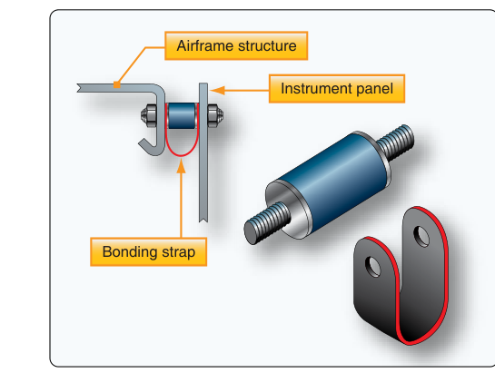
Every time an aircraft taxis over a rough ramp, experiences turbulence, or makes a firm landing, the airframe transmits vibration and shock loads through its structure. While the airframe is designed to handle these forces, the delicate gyroscopic and pressure-sensing instruments mounted on the instrument panel are not nearly as tolerant. Shock mounting systems serve as the critical buffer between the raw mechanical environment of an airframe and the precision mechanisms that pilots depend on for safe flight. For the Aviation Maintenance Technician (AMT) working on airframe systems, understanding why shock mounts are required, how they work, and what standards govern their installation is both a regulatory necessity and a matter of flight safety.
This article provides a thorough treatment of instrument panel shock mounting requirements, grounded in FAA airframe maintenance standards, 14 CFR, and the Aircraft Instrument Systems guidance found in the FAA Aviation Maintenance Handbook series (FAA-H-8083-30/31). Whether you are preparing for the AMT Airframe knowledge test or refreshing your practical skills, this material will give you the depth needed to work on these systems confidently.
Why Instruments Need Shock Protection
Modern flight instruments — particularly gyroscopic instruments such as the attitude indicator, heading indicator, and turn coordinator — rely on precisely balanced rotating masses spinning at thousands of RPM. Accelerometers, altimeters, airspeed indicators, and vertical speed indicators depend on finely calibrated aneroid capsules and precision linkages. Even small, repetitive vibrations can cause cumulative wear on pivot bearings, loosen calibration adjustments, and introduce errors into instrument readings. High-amplitude shock loads, such as those experienced during hard landings or ground operations on rough surfaces, can permanently damage these mechanisms.
Vibration in reciprocating-engine aircraft is particularly problematic because piston engines produce cyclical power pulses that generate broad-spectrum vibration across the airframe. Turbine-powered aircraft generate their own characteristic vibration signatures. In either case, the instrument panel — typically a flat panel bolted to the forward fuselage structure — acts as a direct transmission path for these vibrations unless some form of isolation is interposed between the panel and the structure.
How Shock Mounting Systems Work
A shock mount is essentially an energy-absorbing isolator placed between the instrument panel (or an individual instrument) and the surrounding airframe structure. Most shock mounts used in general aviation instrument panels rely on rubber or elastomeric elements in shear or compression. These materials have natural damping properties: they deform under load, absorbing vibrational energy and converting it to heat rather than transmitting it to the instrument.
There are two common approaches to shock mounting in light aircraft instrument panels:
- Panel-level shock mounting: The entire instrument panel assembly is isolated from the airframe using shock mounts at several attachment points. This approach isolates all instruments simultaneously. The panel typically floats within the forward fuselage structure, restrained by elastomeric grommets or specialized shock mount assemblies at each corner or attachment bracket.
- Individual instrument shock mounting: Each instrument is separately mounted to the panel using a shock-mounted ring or tray. This is common when a rigid subpanel carries some instruments while others require additional isolation. Some instruments, such as certain gyroscopic units, are supplied by the manufacturer with their own integral shock mount provisions.
Shock mounts used at the panel level commonly consist of a metal inner sleeve bonded to an outer metal shell by a vulcanized rubber element. Bolts pass through the inner sleeve to attach to the airframe structure, while the panel attaches to the outer shell — or the arrangement is reversed depending on design. The rubber element handles vibration in all axes: vertical, lateral, and longitudinal. Well-designed elastomeric mounts provide effective isolation across a wide frequency range while still keeping the panel securely restrained against large deflections.
Regulatory and Design Requirements
The foundation for instrument installation requirements in certificated aircraft lies in 14 CFR Part 23 (airworthiness standards for normal, utility, acrobatic, and commuter category airplanes) and Part 25 (transport category airplanes). These parts contain equipment installation provisions (such as those found in the §1301 and related sections of each part) generally requiring that installed equipment function properly under the vibration and operating conditions the aircraft is expected to experience, and that its installation not adversely affect other systems. While these certification standards guide manufacturers during initial design, they also set the baseline that AMTs must respect when performing maintenance, alterations, or replacements.
For maintenance personnel, 14 CFR Part 43 governs the actual maintenance work. Any replacement of a shock mount must restore the aircraft to its original or properly approved design standard. Substituting shock mounts of a different durometer rating, different geometry, or different load-carrying capacity than specified in the aircraft manufacturer's maintenance manual is not acceptable. The aircraft maintenance manual (AMM) or Instructions for Continued Airworthiness (ICA) will specify the correct part numbers, installation torque values, and any special procedures for the shock mount hardware.
The FAA Aviation Maintenance Handbook (FAA-H-8083-30, General) and the Airframe Handbook (FAA-H-8083-31) provide general guidance on instrument installation and vibration isolation principles. These references emphasize that elastomeric mounts degrade over time due to ozone exposure, fluid contamination (oil, hydraulic fluid, fuel), and simply aging — making periodic inspection essential.
Key Numbers and Rules
- Durometer rating: Rubber shock mounts are commonly specified by hardness using a durometer scale (such as Shore A), which is standard industry practice for elastomeric isolators. Substituting mounts with incorrect hardness changes the vibration isolation characteristics and may void airworthiness. Always use the manufacturer's specified part number.
- Bonding integrity: The bond between rubber and metal in an elastomeric mount must be intact. Any separation (de-bonding) is cause for rejection and replacement. Even partial de-bonding allows metal-to-metal contact under load.
- Compression set: Rubber under sustained load takes a permanent set. Shock mounts that appear overly compressed or flattened have lost their isolation effectiveness and must be replaced per the AMM interval or condition requirements.
- Fluid contamination: Petroleum-based fluids (fuel, oil, hydraulic fluid) rapidly degrade many elastomeric compounds, causing swelling, softening, or cracking. Contaminated mounts must be replaced immediately.
- Cracks and tears: Any visible cracking, checking, tearing, or chunking of the rubber element is cause for rejection. Minor surface crazing alone may be within limits per some manufacturer guidance — consult the AMM.
- Torque values: Fasteners attaching shock mounts to the panel or structure must be torqued to the values specified in the AMM. Over-torquing compresses the rubber element excessively, eliminating its isolation function. Under-torquing allows panel movement that can stress instrument connections.
- Electrical bonding: Some designs require a separate electrical bonding strap across the shock mount to ensure the instrument panel remains properly grounded, since the rubber element is an electrical insulator. Verify that bonding straps are intact and properly attached.
Inspection Practices
During routine inspections, the AMT should examine each shock mount visually for signs of rubber degradation: cracking, swelling, de-bonding, compression set, or contamination. Gently manipulating the panel (where access permits) can reveal excessive looseness — a sign of deteriorated or failed mounts — or conversely, a panel that is rigidly fixed because mounts have hardened and lost compliance. Either condition impairs instrument protection.
Instrument panel wiring and plumbing connections (static lines, pitot lines, gyro vacuum or pressure lines) must have sufficient slack and routing flexibility to accommodate the small deflections the shock-mounted panel undergoes in normal operation. If these lines are routed too tightly, they can transmit vibration directly to the instruments, defeating the purpose of the shock mount, or they can fatigue and crack at connection points. Always inspect these connections for chafing and fatigue when working near a shock-mounted panel.
Alterations and Repairs
Replacing worn shock mounts with identical manufacturer-approved parts is a maintenance action that typically falls within the scope of an appropriately rated AMT. However, changing the shock mounting system design — for example, modifying the number of mount points, changing mount geometry, or installing a different type of isolation system — constitutes a major alteration. Major alterations to instrument panels must be accomplished using FAA-approved data and documented on FAA Form 337 in accordance with 14 CFR Part 43 (including Appendix A and Appendix B), or under a Supplemental Type Certificate issued per 14 CFR Part 21, Subpart E, where applicable. The AMT must ensure proper documentation and return-to-service authorization for any alteration.
Common Test Traps
- Assuming any rubber mount will work: The FAA knowledge test may present scenarios where a mechanic substitutes a visually similar mount without checking the part number. This is incorrect — always match the manufacturer's specified part number for the correct durometer and geometry.
- Ignoring electrical bonding: Shock mounts electrically isolate the panel from the airframe. Failing to reinstall or inspect bonding straps after shock mount replacement creates a grounding deficiency that can cause avionics interference or instrument errors.
- Over-torquing fasteners: A common error is applying standard structural torque values to shock mount fasteners without consulting the AMM. Over-torquing eliminates the rubber's compliance, making the mount rigid and defeating its purpose.
- Overlooking plumbing and wiring slack: After panel shock mount replacement, static lines, pitot lines, and gyro plumbing must be verified to have adequate slack. Tight connections transmit vibration directly, bypassing the isolation system.
- Treating surface crazing as always acceptable: Some students assume any surface degradation short of a full crack is acceptable. In reality, acceptability depends on manufacturer guidance in the AMM — surface crazing may be within limits or may be a rejection criterion depending on the specific aircraft and mount design.