Most light training aircraft carry two distinct power sources for their gyroscopic flight instruments: a vacuum (suction) system and an electrical system. The attitude indicator, heading indicator, and turn coordinator all rely on gyroscopic principles to sense aircraft motion, but they do not all draw from the same power supply. This deliberate redundancy is a core element of cockpit design philosophy — if one system fails, the other may still provide usable information. Understanding which instrument runs on which system, how each system operates, and what to expect when one fails is fundamental knowledge for the private pilot certificate and, more importantly, for safe flight in reduced visibility conditions.
This article breaks down both systems mechanically, compares their reliability characteristics, and explains the practical and regulatory implications you need to know for the FAA knowledge test and real-world flying.
How the Vacuum System Works
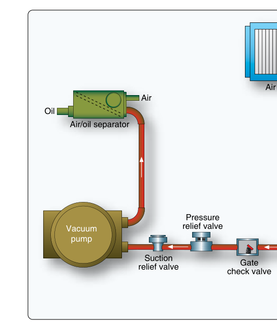
The vacuum system uses a engine-driven vacuum pump — usually a dry-type vane pump mounted directly to the accessory section of the engine — to evacuate air from the instrument cases. As the pump draws air out, outside air rushes through a filter, passes over the gyroscope rotor buckets, and spins the gyro at high speed before being expelled. The suction gauge in the cockpit shows the differential pressure, typically measured in inches of mercury (in. Hg). Most light aircraft gyros are designed to operate within a suction range of approximately 4.5 to 5.5 in. Hg; consult the aircraft's Pilot's Operating Handbook (POH) for the exact limits because values vary by aircraft and instrument model.
The engine-driven pump is the most common suction source in single-engine aircraft. Some older aircraft used a venturi tube mounted externally on the fuselage; airflow through the venturi created suction by Bernoulli's principle. Venturi systems have a critical drawback: they require the aircraft to be moving through the air at sufficient speed, so the gyros do not reach operating speed until several minutes after takeoff, and they may ice over in icing conditions, causing total suction loss at the worst possible moment.
In a standard vacuum system, the attitude indicator (AI) and the heading indicator (HI) — also called the directional gyro (DG) — are powered by vacuum. The gyro rotors in both instruments spin at thousands of revolutions per minute. The AI uses a gyro oriented in the vertical plane to display pitch and bank; the HI uses a horizontally spinning gyro to maintain a stable directional reference during turns and maneuvering, avoiding the oscillation and turning errors inherent in the magnetic compass, though it must still be periodically realigned with the compass to correct for precession.
How the Electrical System Powers Gyroscopic Instruments
Electrically driven gyroscopic instruments contain a small electric motor inside the instrument case that spins the rotor directly. These instruments draw power from the aircraft's main electrical bus, which is supplied by the alternator (or generator) and backed up by the battery. Because they are powered independently of the engine-driven vacuum pump, electrically driven instruments continue to function even if the vacuum system fails — provided electrical power is maintained.
The primary electrically driven gyroscopic instrument in most light aircraft is the turn coordinator (TC). The turn coordinator senses both rate of turn and, because its gyro is canted approximately 30 degrees from horizontal, it also provides an indirect indication of roll rate during entry and recovery. The miniature airplane in the display shows rate of turn; the inclinometer (ball) shows coordination. The turn coordinator is deliberately placed on a different power system than the AI and HI so that a vacuum failure does not leave the pilot with zero gyroscopic reference.
Some modern aircraft and glass cockpit installations reverse the philosophy or add additional redundancy. In aircraft equipped with standby attitude indicators, the standby unit is often electrically driven and battery-backed to provide attitude information even in a complete alternator failure scenario. Electric attitude indicators are also standard in many twin-engine aircraft on one side of the panel.
Comparing the Two Systems
Each system has its own failure profile, and a thorough pilot understands both.
Vacuum system vulnerabilities: The engine-driven pump is a wear item with a finite service life, and it can fail abruptly without warning. A sheared drive coupling, contaminated pump, or broken vane can stop suction instantly. Because the vacuum system is engine-driven, the AI and HI will slowly spin down and may continue to show plausible but incorrect information for several minutes after pump failure — this insidious error is the most dangerous aspect of vacuum failure. The pilot may not notice the failure until the gyros precess enough to create an obvious conflict with other cues. A suction gauge scan is essential during any IMC flight, and many instructors teach checking it on every instrument scan cycle.
Electrical system vulnerabilities: Electrical failures typically involve an alternator failure, which the ammeter or loadmeter will reveal. After alternator failure, the battery continues to supply power but for a limited time — typically 30 minutes or less at normal electrical loads, though this depends on battery condition and the number of items powered. Unlike a slow gyro spin-down, electrically driven instruments usually fail more abruptly when power is lost. However, because the battery is a separate energy reservoir, a broken alternator belt does not simultaneously kill the vacuum pump, and vice versa.
Summary comparison:
- Attitude Indicator (AI): Typically vacuum-driven; fails slowly and deceptively after vacuum loss.
- Heading Indicator (HI): Typically vacuum-driven; same failure mode as AI.
- Turn Coordinator (TC): Typically electrically driven; fails more abruptly on electrical failure but provides gyroscopic backup if vacuum fails.
- Magnetic Compass: Requires no vacuum or electrical power; always available but subject to oscillation, turning errors, acceleration errors, and magnetic deviation.
Why This Matters for Safety
The split-system design ensures that no single failure leaves a pilot with zero gyroscopic reference. If the vacuum pump fails in IMC, the turn coordinator still functions, allowing the pilot to execute a controlled turn and maintain coordination while relying on the magnetic compass for directional information — a technique sometimes called partial-panel flying. The FAA Airplane Flying Handbook covers partial-panel procedures extensively because spatial disorientation following instrument failure is a recognized cause of fatal accidents.
Recognizing a vacuum failure quickly is the critical skill. Pilots should watch for an AI that seems to show a wings-level attitude while the aircraft is clearly in a turn, or an HI that stops precessing normally. Cross-checking against the turn coordinator and magnetic compass can expose the discrepancy. The suction gauge is the first line of defense — a reading outside the green arc demands immediate attention and, if in IMC, a priority declaration and transition to partial panel.
Key Numbers and Rules
- Normal vacuum system operating range: approximately 4.5 to 5.5 in. Hg (verify in POH).
- Gyros typically require 3 to 5 minutes of warm-up after engine start to reach operational speed — avoid relying on the AI immediately after startup.
- Heading indicator must be aligned with the magnetic compass during preflight and realigned approximately every 15 minutes in flight to correct for gyroscopic precession.
- Battery endurance after alternator failure is scenario-dependent but commonly cited as approximately 30 minutes at normal electrical loads — reduce load by shedding non-essential equipment to extend this window.
- The turn coordinator's miniature aircraft wings aligned with the standard-rate turn marks indicate a 3-degree-per-second (360° in 2 minutes) rate of turn.
- There is no FAA-mandated VFR requirement to carry gyroscopic instruments; they are required for IFR flight under 14 CFR 91.205(d).
Common Test Traps
- Which instrument is electrically driven? The FAA knowledge test frequently asks students to identify the turn coordinator as electrically driven and the AI/HI as vacuum-driven. Do not confuse the turn coordinator with the older turn-and-slip indicator — either type may appear on an exam, but the modern turn coordinator is the standard electrically driven unit.
- Vacuum failure deception. A common trap question describes an aircraft in a prolonged turn while the AI shows wings level — this describes vacuum failure and gyro spin-down, not a functional instrument.
- Venturi tubes vs. engine-driven pumps. The FAA may test whether students understand that venturi tubes do not provide suction on the ground or at slow airspeeds, unlike engine-driven pumps which provide suction as soon as the engine runs.
- Suction gauge green arc. Students sometimes confuse a low suction reading (pump failure or blocked filter) with a high suction reading (blocked outlet or sticky relief valve). Both are outside normal limits; both cause instrument errors, but in opposite ways — low suction means gyros spin too slowly, high suction can damage gyro bearings.
- Compass errors vs. gyro errors. The magnetic compass is not gyroscopic and does not depend on either power system, but it has its own errors (northerly turning error, acceleration/deceleration error, deviation) that make it unreliable as a primary directional reference in turns — hence the importance of the HI under normal conditions and the turn coordinator for partial-panel work.
Putting It Together in the Cockpit
A complete preflight instrument check includes verifying that the suction gauge reads in the green arc after engine start, confirming the AI erects to level and shows correct bank during taxi turns, and verifying the turn coordinator's ball and miniature aircraft respond correctly during ground turns. After takeoff, allow a few minutes for gyros to fully stabilize, then align the HI to the compass in straight, level, unaccelerated flight. During flight, incorporate the suction gauge in your regular instrument scan — it takes only a glance and can give you early warning of a developing failure. By understanding exactly why each instrument is on its own power supply and precisely how each system can fail, you move from memorizing facts to genuine airmanship.