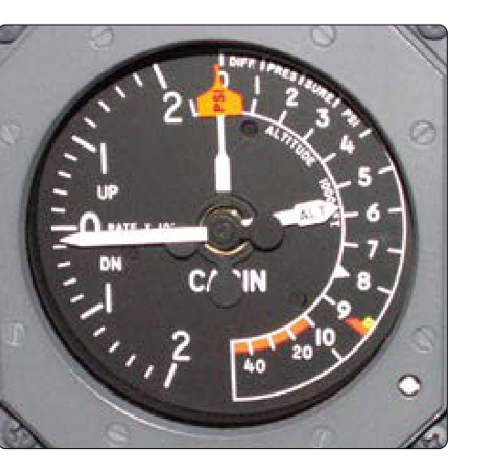
The vertical speed indicator (VSI) — sometimes called a rate-of-climb indicator or variometer — is one of the six flight instruments found in nearly every certified aircraft cockpit's "six-pack," though it is classified as a supporting instrument for pitch rather than a primary instrument in the primary/supporting instrument scan. While the altimeter tells you where you are vertically, the VSI tells you how fast you are moving vertically. That distinction is critically important for instrument flight, traffic avoidance, and smooth, professional aircraft control. For airframe technicians, understanding exactly how this deceptively simple instrument works is essential for accurate troubleshooting, inspection, and sign-off.
The VSI operates on a purely pneumatic principle — no electrical power required in its basic form. It compares the instantaneous static pressure acting on a diaphragm against a slightly delayed version of that same static pressure leaking through a calibrated orifice (or capillary). The difference in pressure between these two pathways drives the instrument's needle. When you understand that elegant simplicity, the VSI's normal behavior, its lag characteristics, and the failure modes that plague it all make immediate sense.
How the VSI Works
Inside the instrument case, there are two pneumatic connections to the same static source: one that goes directly into the interior of an aneroid capsule (or diaphragm), and one that fills the surrounding sealed case. The critical difference is that the case is not connected directly — static air must enter and exit the case only through a precisely sized calibrated leak, sometimes called a capillary or metering unit.
When the aircraft is in level, unaccelerated flight, the static pressure is constant. The pressure inside the capsule and the pressure in the case are equal, so the capsule experiences no differential pressure. The needle reads zero — no climb, no descent.
When the aircraft climbs, ambient static pressure decreases. The capsule, connected directly to static, senses this lower pressure immediately and begins to collapse (or expand, depending on design). The case, however, can only bleed its slightly higher stored pressure out through the calibrated orifice at a controlled rate. This creates a pressure differential between the capsule interior (lower pressure) and the case (slightly higher, lagging pressure). That differential is mechanically linked through a series of gears and levers to the instrument needle, deflecting it to indicate a climb.
Conversely, during a descent, static pressure increases. The capsule expands immediately, but the case pressure lags behind, now being at a lower value than the capsule. The resulting differential pushes the needle downward into the descent region of the dial.
The rate of the needle's deflection is directly proportional to the rate at which pressure is changing — in other words, how fast you are climbing or descending. A faster climb creates a larger instantaneous differential, producing a larger needle deflection. The calibrated orifice is engineered so that the relationship between pressure differential and needle deflection corresponds to specific feet-per-minute (fpm) values, typically ranging from 0 to 2,000 fpm or 0 to 4,000 fpm on the dial.
The Calibrated Leak in Detail
The calibrated orifice (capillary) is the heart of the instrument's design. It is a carefully sized restriction — often a sintered metal plug, a drilled orifice, or a glass capillary tube — that allows air to flow at a predictable, controlled rate relative to the pressure difference across it. The size and characteristics of this orifice determine the instrument's calibration and its lag characteristics.
Temperature affects air viscosity, which affects the flow rate through the orifice at a given pressure differential. Higher-quality VSIs use a metering unit that incorporates a bimetallic compensating element to partially correct for temperature-induced viscosity changes. This compensation keeps the readings more accurate across a wide range of operating altitudes and temperatures — an important consideration for certificated instruments operating per 14 CFR Part 23 or Part 25 standards.
Instantaneous Vertical Speed Indicator (IVSI)
The standard VSI has a well-known limitation: lag. Because the case pressure must physically leak through the calibrated orifice, there is a brief delay — typically 6 to 9 seconds — before the needle stabilizes on the correct rate during a change in pitch attitude. During rapid maneuvers, the needle continues to creep even after the pilot has established a new pitch attitude, which can be disorienting on instruments.
The Instantaneous Vertical Speed Indicator (IVSI) addresses this problem with the addition of one or two small dashpot accelerometers — tiny pistons inside cylinders — connected in parallel with the capsule. When the aircraft pitches up or down, inertia causes these pistons to move, immediately injecting or withdrawing a small volume of air to create an initial pressure pulse inside the capsule. This gives the needle an immediate preliminary deflection in the correct direction, dramatically reducing perceived lag at the onset of a climb or descent. The standard pneumatic pressure-differential principle then takes over and maintains the accurate rate indication.
Technicians should be aware that IVSIs are more complex mechanically, more susceptible to damage from rough handling on the bench, and must be re-certified if the dashpot mechanism is disturbed. They are common in turbine aircraft and high-performance general aviation aircraft used for IFR operations.
Static System Connection and Failure Modes
Because the VSI depends entirely on the static pressure system, any fault in that system directly affects VSI performance. Common failure scenarios include:
- Blocked static port: If the static port becomes obstructed (ice, debris, or a forgotten pitot cover over a combined port), the static pressure inside the capsule cannot change. The VSI needle freezes at zero regardless of actual climb or descent rate. This is a critical in-flight emergency scenario.
- Static system leak: A leak inside the aircraft (a cracked line, loose fitting, or open drain) introduces cockpit pressure into the static system. Because cabin pressure changes as the aircraft climbs — but more slowly and with a different gradient than outside — the VSI will give erroneous, usually low, rate indications. The altimeter and airspeed indicator will also be affected.
- Alternate static source: When an alternate static source (usually inside the cockpit) is selected, the slightly different pressure environment means the VSI may read a momentary transient as the pressure equalizes to the new source, then stabilize at a slightly different zero point.
- Instrument case leak: A leak in the VSI instrument case itself eliminates the sealed reference volume. If the case pressure equalizes as fast as the capsule, there is no differential and the needle reads zero even during climbs and descents. The VSI appears functional on the ground but is useless in flight.
Why It Matters — Safety and Airworthiness
For instrument-rated pilots, the VSI is indispensable for executing smooth, precise altitude changes during approaches, holds, and en-route cruise. Abrupt altitude deviations in controlled airspace can generate TCAS advisories or ATC conflicts. The VSI helps pilots set and maintain specific climb and descent rates with confidence.
For airframe technicians, a malfunctioning VSI has real safety implications. A stuck or erratic VSI may go unnoticed by a pilot during preflight, only to become misleading during IFR operations. 14 CFR Part 91 requires that all instruments required for the flight be operative. During an IFR Part 91 operation, a non-functional VSI is not explicitly listed as required by 14 CFR 91.205, but it is required for IFR flight under the instrument requirements and must be working for the aircraft to be airworthy in many IFR contexts. Technicians must inspect static connections at every opportunity, verify zero indication on the ground with no wind, and check for smooth needle response during a gentle breath-test through the static system (per approved maintenance data).
Key Numbers and Rules
- Standard VSI lag: approximately 6–9 seconds before the needle stabilizes after a pitch change.
- Typical VSI range: 0–2,000 fpm for most general aviation aircraft; 0–4,000 fpm or higher for higher-performance types.
- IVSI dashpot response: near-instantaneous preliminary deflection, typically less than 1 second.
- Instrument case must be sealed: any case leak will cause a zero-reading VSI regardless of actual vertical speed.
- Static system leak test: performed per the aircraft maintenance manual; 14 CFR 91.411 and Part 43 Appendix E govern the required altimeter and static system tests, though VSI accuracy itself is not explicitly tested under that regulation.
- No electrical power required: standard VSI is purely pneumatic; it remains functional during electrical failures (unlike attitude indicators that rely on vacuum/electric gyros, or glass cockpit displays).
Memory Aid
"Direct to the diaphragm, slow through the leak" — Static pressure reaches the capsule/diaphragm directly and immediately, but must leak slowly through the calibrated orifice to reach the case. The difference between "now" and "a moment ago" is what the needle measures. If you remember this phrase, you can reconstruct every normal behavior and failure mode of the VSI from first principles.
Common Test Traps
- Trap 1 — "The VSI needs electrical power." A standard pitot-static VSI requires no electrical power. Only electronic or digital VSI displays require electricity. Do not confuse the instrument with glass-panel representations of it.
- Trap 2 — "A blocked static port makes the VSI read incorrectly." More precisely, it makes the VSI read zero — frozen at zero — not some random wrong number. Similarly, the altimeter freezes at the altitude where the blockage occurred.
- Trap 3 — "The VSI reads accurately immediately." The standard VSI has a 6–9 second lag. Technicians and pilots should not rush to correct an attitude based on a VSI needle that is still moving toward its stable value.
- Trap 4 — "A leaking instrument case causes a high VSI reading." In fact, a case leak causes a zero or near-zero reading, because the pressure differential that drives the needle cannot be maintained when the reference volume is open to the atmosphere.
- Trap 5 — "The IVSI eliminates all lag." The IVSI greatly reduces initial lag through its dashpot accelerometers, but it does not eliminate the underlying pneumatic principle or all lag in sustained maneuvers. The dashpot gives a jump-start to the needle; the capillary system still governs the sustained reading.