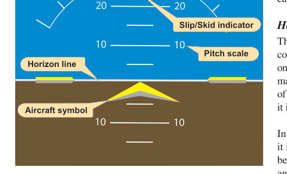
The attitude indicator (AI) — sometimes called the artificial horizon — is one of the most important flight instruments in the cockpit. When you can't see the natural horizon through the windshield, the attitude indicator tells you whether the aircraft's nose is pitched up, pitched down, or banked to either side. Understanding how the instrument works internally, and where it can mislead you, is essential both for the FAA knowledge test and for safe flight in actual instrument conditions.
Most private pilot training aircraft use a gyroscopic attitude indicator driven either by a vacuum (suction) system or by electrical power. Regardless of the power source, the core principle is the same: a rapidly spinning gyroscope resists changes to its orientation — a property called gyroscopic rigidity in space — and that resistance is what keeps the instrument's miniature airplane symbol aligned with the real horizon even when the aircraft maneuvers around it.
How the Attitude Indicator Works
Inside the attitude indicator is a gyroscope rotor spinning at very high speed — typically 10,000 to 18,000 RPM in vacuum-driven units. The rotor is mounted in a gimbal system that allows it to remain spatially fixed while the instrument case (attached to the aircraft) moves around it. Because the gyro is rigid in space, the miniature airplane symbol on the face of the instrument reflects the actual pitch and bank of the aircraft relative to a stable reference.
In a vacuum-driven system, engine-driven vacuum pumps (or venturi tubes on older aircraft) draw air through the instrument. Jets of air impinge on buckets cut into the edge of the gyro rotor, spinning it up and keeping it at operating speed. The typical operating vacuum is 4.5 to 5.5 inches of mercury (verify the exact range in your aircraft's POH), and a suction gauge on the instrument panel confirms the system is producing adequate vacuum. If vacuum drops below the minimum value, the gyro slows down, and the attitude indicator becomes unreliable — often without any obvious indication other than the suction gauge reading.
Electrically driven attitude indicators use an electric motor to spin the gyro rotor. These are common on aircraft with electric standby instruments and glass cockpit systems. The behavior and error characteristics are broadly similar, though the specific failure modes differ slightly.
Gyroscopic Rigidity and Precession
The attitude indicator relies on gyroscopic rigidity in space: a spinning gyroscope tends to maintain its orientation in inertial space unless acted upon by an external force. This is the same principle that keeps a bicycle wheel upright while spinning.
However, gyroscopes are not perfectly rigid. They can be tilted or rotated over time by several forces, and this leads to precession errors. Precession is the tendency of a gyroscope to react to an applied force not where the force is applied, but 90 degrees later in the direction of rotation. In practical terms, this means that over time or during specific maneuvers, the gyro's reference plane can drift slightly away from the true horizon, introducing a small error in what the instrument displays.
Types of Precession Errors
Real precession (drift) occurs due to bearing friction and imperfect balance in the gyro. Over time, this causes the gyro to slowly wander from its original alignment. Most attitude indicators include an erecting mechanism — typically small pendulous vanes that are moved by gravity — that continuously re-erects the gyro toward the true vertical. This corrects slow drift but cannot correct fast precession during dynamic maneuvers.
Apparent precession occurs because the gyro is rigid in inertial space, but the Earth rotates beneath it. As the Earth turns, the gyro maintains its original orientation while the horizon below changes. This effect is very slow (roughly one revolution per 24 hours) and has minimal impact during a typical flight.
Acceleration errors are the most operationally significant precession errors. During rapid acceleration or deceleration on the ground or in flight, inertial forces act on the pendulous vanes or erecting mechanism, causing the gyro to precess slightly. The classic example occurs during a rapid acceleration on the takeoff roll: the attitude indicator may pitch up slightly, indicating a false climb. Conversely, rapid deceleration can cause a false pitch-down indication. These errors are temporary and small, but a student who hasn't been briefed can misinterpret them.
Turning errors in the attitude indicator are less significant than in the magnetic compass or the turn coordinator, but the erecting mechanism's pendulous vanes can be affected by centrifugal force during prolonged banked turns. During a prolonged steep turn, centrifugal force tilts the pendulous vanes outward, causing the erecting mechanism to precess the gyro slightly. The result can be a small bank or pitch error that accumulates during long, continuous turns. This is one reason pilots should not use the attitude indicator as the sole reference for very long turns without periodic cross-checking.
Gyroscopic Tumbling and Gimbal Limits
The gimbal system that allows the gyro to remain spatially fixed has physical limits. Most attitude indicators have a pitch limit of approximately ±60 to 70 degrees and a bank limit of approximately ±100 to 110 degrees. If the aircraft exceeds these limits — for example, in unusual attitude recovery training or aerobatics — the gyro can tumble (topple), meaning the gimbals reach their stops and the gyro is forced out of alignment. After tumbling, the erecting mechanism will re-erect the gyro, but this takes time — typically 5 minutes or more for the instrument to return to accurate operation. Attitude indicators intended for aerobatic aircraft are built to much wider gimbal limits or use caging mechanisms to prevent tumbling.
Vacuum System Failures
Because most attitude indicators in single-engine training aircraft are vacuum driven, a vacuum pump failure is a significant in-flight emergency. The gyro will gradually slow down and the instrument will become unreliable, but it often doesn't fail instantly or obviously. The miniature airplane may slowly drift but still appear somewhat plausible, which is why checking the suction gauge regularly is a critical scan habit. In instrument meteorological conditions (IMC), a failed vacuum-driven AI without a backup electric attitude source is an immediate emergency. This is a key reason the FAA requires an understanding of vacuum system limitations for the private pilot certificate.
Why It Matters
The attitude indicator is the primary reference for aircraft control in instrument meteorological conditions (IMC). Without a reliable horizon — either natural or artificial — spatial disorientation can occur within seconds. The human vestibular system is easily deceived by sustained turns, acceleration, and the absence of outside visual references. Trusting the instruments, especially the attitude indicator, over physical sensations is one of the most important skills instrument-rated pilots develop. Even for VFR pilots, an inadvertent entry into IMC makes the attitude indicator the difference between controlled flight and a potentially fatal loss of control.
Key Numbers and Rules
- Normal operating vacuum: 4.5 to 5.5 inches of mercury (check the suction gauge in your POH)
- Typical gyro rotor speed: 10,000–18,000 RPM (vacuum driven)
- Pitch/bank limits before tumbling: approximately ±60–70° pitch, ±100–110° bank (varies by instrument)
- Re-erection time after tumbling: typically 5 minutes or more
- Acceleration error on takeoff: brief false pitch-up indication during rapid acceleration
- Turning error: small accumulated error during prolonged steep turns due to centrifugal force on erecting vanes
- Power-up time: allow at least 5 minutes for the gyro to spin up to operating speed before relying on the instrument for flight
Memory Aid
To remember the two primary properties of gyroscopes that make the attitude indicator work — and fail — use R-P: Rigidity and Precession.
- R — Rigidity in space: the spinning gyro maintains its orientation, providing a stable horizon reference.
- P — Precession: applied forces cause the gyro to drift 90° from where the force is applied, introducing errors during acceleration, deceleration, and prolonged turns.
When you see the attitude indicator doing something unexpected, ask: "Is this real aircraft attitude, or is Rigidity or Precession fooling me?" Then cross-check the altimeter, airspeed, and turn coordinator to confirm.
Common Test Traps
- Acceleration error direction: The FAA often asks which direction the AI errs during acceleration. The answer is a false pitch-up (nose-high) during acceleration and a false pitch-down during rapid deceleration — not the reverse.
- Vacuum vs. electrical failure: Know that a vacuum pump failure does not immediately kill the attitude indicator; the gyro slowly winds down. Students often assume the instrument fails instantly — it does not, which makes it more insidious.
- Re-erection time: After tumbling or a long vacuum interruption, the AI needs several minutes to re-erect. Many students assume it corrects instantly when power is restored.
- Which instruments are vacuum-driven: On a typical six-pack panel, the attitude indicator and heading indicator are vacuum driven; the turn coordinator is usually electrically driven. This matters for partial-panel scenarios on the test.
- Gimbal limits and aerobatics: The standard attitude indicator is not approved for aerobatics. Exceeding pitch and bank limits causes tumbling and requires a warm-up period before the instrument is reliable again — a detail the FAA tests in scenario-based questions.