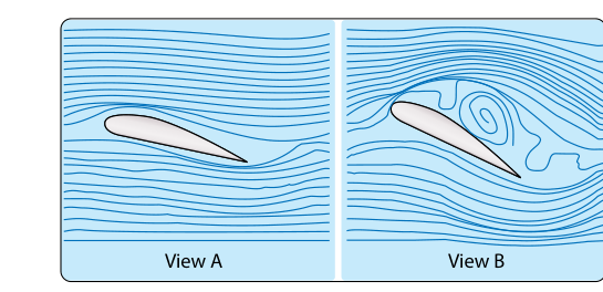
Every pilot learns that wings produce lift and drag, but the real story unfolds in a paper-thin zone of air that most pilots never see and few fully understand. The boundary layer is the region of airflow that forms directly against the wing's surface, extending outward only until the local velocity matches the undisturbed free-stream airspeed. Within that slender zone, viscous friction between air molecules and the wing surface governs skin-friction drag, determines when flow separates, controls stall onset, and explains why contamination as thin as a coat of frost can be lethal. For flight and ground instructors, the boundary layer is not an abstract physics curiosity—it is the physical foundation beneath every lesson on stalls, drag reduction, high-lift devices, and preflight inspection discipline.
How the Boundary Layer Forms and Grows
Air approaching a wing is initially moving at free-stream velocity with no influence from the surface. The instant it contacts the leading edge, viscosity causes the molecules immediately adjacent to the surface to slow dramatically, essentially reaching zero velocity at the surface itself. This condition is called the no-slip condition. Outward from the surface, velocity increases progressively until it rejoins the free stream. That gradient of velocity defines the boundary layer.
The boundary layer begins extremely thin at the leading edge and thickens as it travels rearward along the chord. Near the leading edge, the flow organizes itself into smooth, parallel sheets in what is called the laminar boundary layer. In this regime, air molecules slide past one another with minimal lateral mixing, and the resulting skin-friction drag is relatively low. The Pilot's Handbook of Aeronautical Knowledge (PHAK, FAA-H-8083-25) describes laminar flow airfoils—such as those used on some general aviation aircraft—as specifically designed to maintain this orderly state over a greater portion of the chord, thereby reducing drag at cruise conditions.
Laminar flow is inherently unstable, however. Surface imperfections, boundary layer thickness itself, and disturbances in the oncoming airflow eventually cause the orderly sheets to break down into chaotic, three-dimensional eddies. This breakdown is called laminar-to-turbulent transition, and the resulting turbulent boundary layer is thicker, mixes energy laterally, and produces higher skin-friction drag. Crucially, though, the turbulent boundary layer carries significantly more momentum than its laminar counterpart. That additional momentum is the key to understanding stall behavior.
The Adverse Pressure Gradient and Flow Separation
As airflow accelerates over the upper surface of a wing, it reaches peak velocity somewhere near the point of maximum camber. Beyond that point, the flow must decelerate to match the lower pressure at the trailing edge region—a condition called an adverse pressure gradient, because the pressure increases in the direction of flow. Moving against a rising pressure costs the boundary layer kinetic energy. If the boundary layer retains enough energy, it stays attached all the way to the trailing edge, and the pressure differential responsible for lift is maintained. If the boundary layer exhausts its energy reserve, it separates from the surface, breaking the smooth pressure distribution and causing lift to collapse. That is the stall.
The critical angle of attack at which this separation becomes catastrophic is typically around 15 to 18 degrees for most general aviation airfoils, though the exact value is airfoil-specific. What matters for instruction is that the stall is defined by exceeding the critical angle of attack, which triggers flow separation—not by airspeed, weight, or load factor alone. Any combination of those factors that forces the wing to the critical angle of attack will stall it, as the PHAK makes clear.
The turbulent boundary layer's higher momentum explains a seemingly counterintuitive fact: a turbulent boundary layer resists separation better than a laminar one and therefore allows the wing to reach a slightly higher angle of attack before stalling. This is the principle behind vortex generators—small delta-shaped fins mounted on the upper wing surface of some aircraft. They deliberately draw high-energy air from outside the boundary layer down into it, energizing the flow and delaying separation. The result is improved low-speed handling and a lower stall speed, at the cost of a small increase in cruise drag.
Drag Components Rooted in Boundary Layer Behavior
Understanding the boundary layer untangles the confusing taxonomy of drag. The PHAK categorizes drag into parasite drag and induced drag. Within parasite drag, profile drag has two components directly traceable to boundary layer physics:
- Skin-friction drag arises from the viscous shear forces within the boundary layer itself. A smooth, laminar boundary layer produces less skin-friction drag; a thick, turbulent one produces more. This is why airframe manufacturers specify smooth paint finishes and why operators must remove even thin surface contamination before flight.
- Pressure drag (form drag) arises when the boundary layer separates from the surface and leaves a turbulent, low-energy wake downstream of the wing. The separated region creates a large difference in pressure between the front and rear of the airfoil. At high angles of attack approaching the stall, pressure drag dominates and rises steeply—exactly when lift is collapsing. The simultaneous spike in drag and collapse of lift is what makes the fully stalled condition so unforgiving.
Induced drag, by contrast, has nothing to do with the boundary layer. It is a consequence of the pressure difference between the upper and lower wing surfaces that causes spanwise flow and wingtip vortices, as described in the PHAK. Instructors should be explicit about this distinction because students frequently conflate the two on knowledge tests.
Reynolds Number: The Governing Parameter
The Reynolds number is a dimensionless ratio that relates inertial forces to viscous forces in a flow and predicts whether the boundary layer will be laminar or turbulent. It increases with airspeed and chord length and decreases with air viscosity. Practically speaking, larger aircraft flying faster operate at higher Reynolds numbers and transition to turbulent flow earlier along the chord. Small, slow aircraft—and scale models—operate at lower Reynolds numbers where laminar flow is more persistent but airfoil behavior can differ markedly from full-scale flight. While pilots do not compute Reynolds numbers operationally, the concept explains why airfoil designs optimized for one speed regime may perform poorly in another, and why wind-tunnel data from small models must be scaled carefully.
Contamination, Icing, and Preflight Implications
Any disruption to the wing surface—frost, ice, snow, bugs, or deteriorating paint—triggers premature laminar-to-turbulent transition and may trip separation earlier along the chord. The FAA has long emphasized that even a thin layer of frost, which feels smooth to the touch, creates surface roughness at a microscopic scale sufficient to destroy laminar flow and reduce lift while increasing stall speed. The clean-aircraft concept and the prohibition on takeoff with frost, ice, or snow adhering to critical surfaces is codified in 14 CFR 91.527 for large and turbine-powered multiengine airplanes, and reinforced under 121.629 and 135.227 for air carrier operations, with further guidance in FAA Advisory Circulars on ground icing. The ground instructor must drive home that this rule is not bureaucratic caution—it is boundary layer physics applied to flight safety.
Key Numbers and Rules
- The boundary layer velocity at the surface equals zero (no-slip condition); velocity increases to free-stream value at the outer edge.
- Critical angle of attack for most general aviation airfoils falls in the range of approximately 15 to 18 degrees, though the exact value is airfoil-specific.
- A turbulent boundary layer resists flow separation better than a laminar one, despite producing more skin-friction drag.
- Vortex generators energize the boundary layer to delay separation and lower effective stall speed.
- Frost or ice on lifting surfaces disrupts the boundary layer and can cause the wing to stall at a lower angle of attack than published performance data reflects.
- Profile drag (skin friction + pressure drag) is the parasite drag component controlled by boundary layer behavior; induced drag is not.
Common Test Traps
- Laminar flow is not universally superior. Less skin-friction drag is offset by earlier flow separation at high angles of attack. Some designs intentionally promote turbulent flow to improve stall margins.
- Stall is defined by angle of attack, explained by flow separation. Knowing only the symptom (high angle of attack) without understanding the mechanism (boundary layer separation) leaves a student unable to reason through unusual stall scenarios.
- Profile drag versus induced drag. Boundary layer physics produces profile drag. Induced drag is a byproduct of lift generation and wingtip vortices—completely separate physics. Many students misattribute one to the other on the Instrument Rating, Commercial Pilot, and Flight Instructor knowledge tests.
- Contamination lowers the published stall angle. Preflight removal of frost and ice is not optional and is grounded in boundary layer mechanics, not merely regulation.
- Vortex generators increase turbulent flow intentionally. Students sometimes assume any turbulence in the boundary layer is undesirable; vortex generators prove otherwise.