Of all the threats to a reciprocating engine's fuel metering system, carburetor icing stands out as particularly insidious — it can occur during cruise flight on a warm, sunny day when a pilot least expects it. For the aviation maintenance technician working on powerplant systems, understanding exactly how and where ice forms inside a carburetor, what conditions promote each type, and what engineering solutions exist to counter it is both a certification exam requirement and a genuine safety imperative. This article examines carburetor icing from a powerplant technician's perspective, grounding every concept in FAA handbook guidance.
The Carburetor's Role and Why Icing Occurs
A float-type carburetor meters fuel into the incoming airstream to create a combustible mixture. To do this, it relies on the Venturi principle: as air accelerates through a narrowed throat, its pressure drops and its velocity rises. Fuel is drawn from the float bowl through jets and discharged into this low-pressure region, where it atomizes and mixes with the air. This physical process has an unavoidable thermal consequence — the drop in pressure causes a corresponding drop in temperature. According to the FAA's Aviation Maintenance Technician Handbook – Powerplant (FAA-H-8083-32), the temperature drop in the venturi and at the throttle valve area can be as much as 60°F (approximately 33°C) below the temperature of the incoming air, though the exact figure can vary by installation and source. When ambient air is moist, this sudden chilling can easily push local temperatures below the freezing point of water even when outside air temperature is well above 32°F.
Three Types of Carburetor Icing
FAA powerplant training materials identify three distinct mechanisms by which ice forms in a carburetor. Each has its own set of atmospheric conditions and its own preferred location inside the unit. A technician who can distinguish among them will be better equipped to diagnose symptoms, perform inspections, and advise operating crews.
1. Fuel Evaporation Ice (Refrigeration Ice)
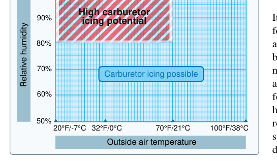
This is the most common and most dangerous type. When liquid fuel is introduced into the airstream and evaporates, it absorbs latent heat from its surroundings — the same principle that makes rubbing alcohol feel cold on skin. Combined with the pressure-drop cooling at the venturi, this evaporative cooling can lower the local temperature dramatically. Ice forms on the walls of the venturi, throttle body, and throttle plate itself. Because this type depends primarily on evaporative cooling rather than on the presence of visible moisture, it can occur in clear air with relative humidity around 50% or higher, depending on temperature as shown on FAA carburetor icing probability charts, and at outside air temperatures ranging from roughly 20°F to 80°F (approximately -7°C to 27°C). The most dangerous band is often cited as 30°F to 40°F (-1°C to 4°C) at high humidity, but significant icing potential exists across a much broader temperature range. This is the type of icing that can catch pilots completely off guard on a clear day.
2. Impact Ice
Impact ice forms when supercooled water droplets — the same droplets associated with structural airframe icing — strike the carburetor air inlet, inlet screen, or other upstream surfaces and freeze on contact. Unlike fuel evaporation ice, this type requires visible moisture: rain, snow, sleet, or flight in clouds containing supercooled droplets. It tends to form at or near the air inlet filter and screen rather than deep inside the carburetor throat. While impact ice can obstruct airflow significantly, it is generally a lesser threat in terms of surprise than fuel evaporation ice because it requires conditions a pilot can often anticipate. Impact ice is most likely in visible moisture at temperatures near or just below freezing, roughly 0°C down to about -10°C, where supercooled droplets are common.
3. Throttle Ice (Pressure Drop Ice)
Throttle ice develops specifically at the throttle valve (butterfly valve) and the area immediately downstream of it. When the throttle is partially closed — as during a low-power descent — the pressure drop across the nearly closed valve is greatest, and the resulting temperature drop is most severe at that point. Water vapor in the incoming air can freeze directly onto the throttle plate and the surrounding throttle bore walls. This type of icing is most hazardous during approaches and descents when power is reduced, and it can cause the throttle to stick or even jam. Throttle ice is differentiated from fuel evaporation ice in that it is driven primarily by pressure-drop refrigeration at the butterfly, not by fuel evaporative cooling.
Symptoms of Carburetor Icing in Service
During engine operation, the primary symptom in a fixed-pitch propeller aircraft is an unexplained, gradual drop in engine RPM. In a constant-speed propeller installation, manifold pressure will decrease while RPM remains nominally constant. In either case the engine may run rough before losing power further. If icing is allowed to progress, the engine may quit entirely. After ice is cleared (for example, by applying carburetor heat), a brief additional RPM drop followed by a rise back toward normal — caused by the ice melting and passing through as water-rich mixture — confirms that icing was the cause. Technicians performing maintenance runs should be alert to these signatures, particularly when conducting ground runs in humid, cool conditions.
Prevention and Control Systems
The FAA's powerplant handbook details several engineered approaches to dealing with carburetor icing, the most widely used of which is the carburetor heat system.
Carburetor Heat
The carburetor heat system routes air over or through a shroud surrounding the exhaust manifold, then directs this pre-heated air to the carburetor air inlet in place of the normal ram-air supply. By raising the temperature of incoming air, the system prevents or melts ice that has already formed. Technicians must ensure that the alternate air door seals fully in both the HEAT and COLD positions, that no cracks exist in the heat muff or exhaust shroud that could admit exhaust gases into the intake air (a carbon monoxide hazard), and that the control cable operates without binding or excessive play. It is important to note that carburetor heat air bypasses the air filter, so using carb heat on the ground where dust is present can allow abrasive particles into the engine — this is a maintenance consideration when evaluating engine wear.
Carburetor heat, when applied, typically causes a slight momentary RPM drop on a normally aspirated engine, with the exact amount varying by aircraft type and installation. This is expected because the heated air is less dense, producing a richer and slightly less powerful mixture. If ice was present, the RPM will drop a bit further as ice melts and then recover. Full carburetor heat should generally be applied — partial heat can sometimes cause ice to form more readily by warming the air just enough to increase moisture content without preventing freezing.
Alternate Air Source
Fuel-injected engines do not have a carburetor venturi or float system, so they are not susceptible to fuel evaporation ice. However, their air intake can still suffer impact ice blockage. Many fuel-injected installations include an alternate air door that opens — either manually or automatically via a spring-loaded door when the main inlet is obstructed — to draw heated air from inside the engine compartment. Technicians should verify that automatic alternate air doors open freely and reseal properly, and that manual controls operate smoothly across the full range of travel.
Induction System Design and Filtration
Aircraft manufacturers may position the air inlet to take advantage of ram-air pressure while minimizing exposure to liquid water. Inlet screens prevent large debris from entering, but they are a prime location for impact ice accumulation. Technicians should inspect screens for damage and ensure drain provisions function correctly. Some installations include alternate induction air boxes that use pre-heated air as a secondary path when the primary inlet is blocked.
Key Numbers and Rules
- Temperature drop: Up to 60°F (33°C) below incoming air temperature can occur in the carburetor venturi and throttle area due to pressure drop and fuel evaporation cooling, though exact figures vary by source and installation.
- High-risk OAT range: Fuel evaporation icing risk exists from approximately 20°F to 80°F (-7°C to 27°C); highest risk is often cited at 30°F–40°F at high relative humidity.
- Humidity threshold: Fuel evaporation ice risk is commonly shown beginning around 50% relative humidity on FAA carburetor icing probability charts, with risk varying by temperature; impact ice requires visible moisture (rain, clouds, freezing precipitation).
- Expected RPM drop: Applying carburetor heat normally produces a slight, aircraft-dependent RPM drop due to reduced air density; additional drop then recovery indicates ice was present.
- Heat muff inspection: Any crack in an exhaust heat muff creates a carbon monoxide contamination risk — a critical safety finding requiring grounding of the aircraft.
- Full vs. partial carb heat: Partial heat can worsen icing by warming incoming air without fully preventing freezing — always apply full heat per the AFM/POH and manufacturer guidance.
Common Test Traps
- Assuming icing only happens in cold weather: Fuel evaporation icing is most notorious for occurring at temperatures well above freezing — up to 80°F OAT. Exam questions often describe a warm, humid day and ask whether icing is possible; the answer is yes.
- Confusing the three types: Fuel evaporation ice, impact ice, and throttle ice each have distinct conditions and locations. Know that impact ice requires visible moisture; the other two do not necessarily.
- Partial carburetor heat: Students sometimes think partial heat is a conservative approach. In fact, partial application can increase icing risk by raising moisture content just above dew point without preventing freezing — full heat is the correct technique.
- Fuel-injected vs. carbureted: Fuel-injected engines are NOT susceptible to fuel evaporation ice but CAN suffer impact ice at the air inlet. Knowing the difference is a frequent exam point.
- Heat muff cracks: Confusing a cracked heat muff as a minor maintenance item is dangerous — it is a carbon monoxide hazard and an airworthiness defect. On the AMT exam, expect questions that test whether you recognize this as a grounding discrepancy.