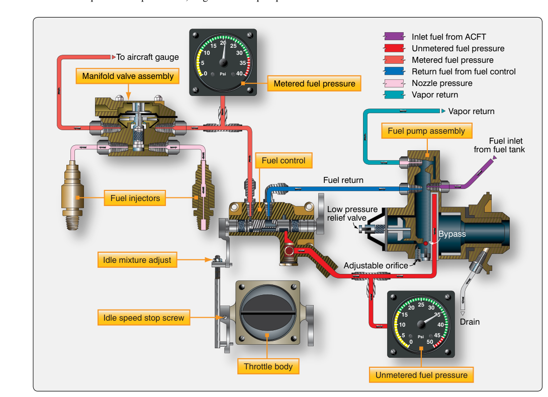
Continuous-flow fuel injection is the predominant fuel metering system found on modern piston-powered general aviation aircraft equipped with fuel-injected engines. Unlike a carburetor, which vaporizes fuel in a venturi before the intake manifold, a continuous-flow injection system delivers a precisely metered, uninterrupted stream of liquid fuel directly to the intake port of each cylinder. This arrangement offers significant advantages in mixture distribution uniformity, throttle response, and — most importantly from a safety standpoint — immunity to the venturi/fuel-vaporization type of carburetor ice formation. For the AMT Powerplant candidate, a thorough understanding of how this system meters, distributes, and controls fuel flow is essential both for the FAA knowledge exam and for real-world maintenance practice.
The Bendix RSA system (and its Continental counterpart, the continuous-flow injector) are the most commonly encountered designs in the general aviation fleet. Although the specific hardware details differ between manufacturers, the fundamental operating principles are consistent across all continuous-flow systems: a fuel-air control unit meters fuel in response to airflow demand, and a flow divider distributes that metered fuel equally to individual injector nozzles at each cylinder.
System Components and How They Work Together
A continuous-flow fuel injection system is typically divided into four major sub-assemblies: the engine-driven fuel pump, the fuel-air control unit (often called the fuel control unit or FCU), the flow divider (also called the fuel manifold valve), and the individual fuel injector nozzles. Each component plays a specific role in transforming raw fuel pressure into a precisely calibrated mixture delivered to each cylinder.
Engine-Driven Fuel Pump
The engine-driven pump is a positive-displacement vane-type pump that provides fuel at a pressure considerably higher than what the injector nozzles require. This excess pressure is managed by a built-in relief valve that routes surplus fuel back to the pump inlet. Because the pump output varies with engine RPM, the relief valve ensures a stable supply pressure to the fuel control unit regardless of engine speed. An auxiliary electric boost pump is installed in parallel to provide fuel pressure during starting, takeoff, and as a backup in the event of engine-driven pump failure. The boost pump is also used during fuel tank switching to prevent vapor lock.
Fuel-Air Control Unit
The fuel-air control unit is the brain of the system. In the Bendix RSA design, incoming air passes through an airflow sensor that uses a venturi and an impact pressure tube to measure the mass of air entering the engine. The unit converts this airflow measurement into a differential pressure signal. On the fuel side, a diaphragm assembly responds to this differential pressure to position a fuel metering valve — the higher the airflow, the wider the metering valve opens, and the more fuel flows through. This elegant pneumatic-hydraulic relationship ensures that fuel flow is always proportional to actual air consumption, which is the definition of correct mixture ratio management.
The mixture control in the cockpit connects mechanically to a separate valve within the FCU. When the pilot leans the mixture, this valve progressively restricts fuel flow by increasing the pressure drop on the metered-fuel side, effectively enrichening or leaning the mixture without affecting the fundamental air-mass sensing mechanism. At the full lean (idle cutoff) position, the valve seats completely, cutting off all fuel flow and stopping the engine cleanly.
The throttle controls a conventional butterfly valve in the air intake portion of the FCU, governing the volume of air that reaches the engine and, by the linked fuel metering mechanism, simultaneously controlling fuel flow. This is why continuous-flow systems provide excellent throttle response: fuel flow changes are essentially instantaneous with throttle movement, because the system reacts to airflow rather than to throttle position alone.
Flow Divider (Fuel Manifold Valve)
Metered fuel leaving the FCU travels to the flow divider, which is typically mounted at a high point on the engine. The flow divider serves two critical functions. First, it distributes fuel equally among all the fuel lines leading to each cylinder's injector nozzle. Second, it contains a spring-loaded diaphragm valve that keeps all lines pressurized and simultaneously opens and closes all nozzle circuits together. When the engine is shut down, this valve closes, which prevents fuel from draining out of the nozzle lines and causing hot-start difficulties from vapor formation in a heat-soaked engine compartment. During starting, the valve opens as soon as fuel pressure rises to a threshold value — which varies by specific engine and injector model and is often considerably higher than a few psi in many Continental and Lycoming applications — ensuring that all cylinders receive fuel at the same time.
Injector Nozzles
The injector nozzles are fixed orifices — they have no moving parts. Each nozzle is precisely calibrated so that, at a given fuel pressure, a specific mass of fuel is delivered. Because all nozzles are identical and are fed from a common manifold at equal pressure, cylinder-to-cylinder fuel distribution is highly uniform. The nozzle discharges liquid fuel into the intake port just upstream of the intake valve, where the low pressure of the incoming air charge atomizes the fuel and mixes it before it enters the combustion chamber. Air bleeds in the nozzle body assist in atomization. Nozzles are color-coded by flow rate and must be replaced only with nozzles of the matching calibration code — mixing nozzle sizes will destroy the uniform distribution that makes the system work correctly.
Why This System Matters for Safety and Performance
The most operationally significant advantage of continuous-flow injection over carburetion is the elimination of venturi-induced carburetor ice. Because fuel does not vaporize inside a venturi in the induction system, the temperature drop that causes classic carburetor ice formation in carbureted engines does not occur in the same way. However, fuel-injected engines are not completely immune to all forms of induction icing — impact ice can still form on the air intake screen or throttle body under certain icing conditions, so pilots and technicians must remain alert to this possibility.
Uniform fuel distribution improves combustion efficiency and reduces the risk of detonation caused by an overly lean cylinder. In a carbureted engine, one or more cylinders may run significantly richer or leaner than others due to manifold geometry; injection systems nearly eliminate this problem. Better distribution also means engine builders can set tighter temperature limits, which extends engine longevity.
From a maintenance standpoint, clogged or partially blocked injector nozzles are a common squawk on fuel-injected engines. A blocked nozzle will lean that cylinder, potentially causing detonation or rough running. Regular nozzle cleaning — following the manufacturer's approved procedure — is a standard maintenance task. Technicians must also be alert to vapor lock concerns, particularly on hot-soaked restarts, and should verify boost pump operation and fuel line integrity when a pilot reports hard starting when the engine is hot.
Key Numbers and Rules
- Flow divider opening pressure: Varies by engine and injector model; this threshold ensures all nozzles open simultaneously during starting.
- Engine-driven pump pressure: Pump output is intentionally higher than system demand; the internal relief valve maintains regulated pressure to the FCU.
- Nozzle calibration: Nozzles are color-coded by flow rate; all nozzles on a single engine must be the same calibration code to maintain uniform distribution.
- Idle cutoff: The mixture lever at full lean physically seats the mixture valve in the FCU, providing a positive fuel shutoff — not merely a reduced-flow position.
- Boost pump usage: Required during engine start, takeoff (per many POH procedures), and anytime the engine-driven pump is suspected of failure or during tank switching to prevent vapor lock.
- Maintenance authority: Per 14 CFR Part 43 (and Part 65, Subpart D, governing A&P mechanic privileges), adjustments to the fuel-air control unit (idle speed, idle mixture, fuel flow) must be performed by a certificated powerplant mechanic following type-certificate data sheet and manufacturer's maintenance manual requirements.
Common Test Traps
- Continuous-flow is NOT the same as timed injection. Fuel delivery is uninterrupted and constant — it does not pulse in sync with the intake stroke. This is a frequent point of confusion with automotive fuel injection systems, which are timed and sequential.
- The injector nozzle has no moving parts. It is a fixed, calibrated orifice. Students sometimes assume it opens and closes like a solenoid valve — it does not. Metering occurs entirely at the FCU.
- The flow divider does NOT meter fuel. It only distributes and pressure-isolates the nozzle circuits. All metering is done upstream at the FCU. Confusing these two components is a common exam error.
- Mixture control works on the fuel side, not the air side. Leaning the mixture does not close an air restriction; it reduces fuel flow through the metering valve. The airflow and sensing mechanism continues to operate normally.
- Hot-start vapor lock is a real concern. When a heat-soaked engine is restarted, fuel in the lines may vaporize. The correct procedure — using the boost pump and following the POH — is essential. Technicians should not confuse a vapor-lock hard-start condition with a flooded engine, as the remedies are different and applying the wrong one makes the situation worse.