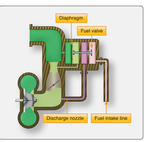
Most pilots and mechanics are familiar with the float-type carburetor — a relatively simple device that relies on atmospheric pressure pushing fuel through a float bowl and venturi. But high-performance reciprocating engines, especially those installed in larger aircraft and operated at varying attitudes, demand more precise and reliable fuel metering. The pressure-injection carburetor answers that demand by using differential air pressures acting on a series of diaphragms and calibrated valves to meter fuel under positive pressure, completely independent of gravity. Understanding its design and operation is essential knowledge for any Aviation Maintenance Technician (AMT) working on powerplant systems.
Pressure-injection carburetors are sometimes called injection carburetors to distinguish them from float carburetors, though they should not be confused with fuel-injection systems, which deliver fuel directly to the cylinders. The pressure-injection carburetor still introduces fuel into the induction airstream — but it does so with remarkable precision, using a closed, pressurized fuel circuit rather than an open float bowl exposed to the atmosphere.
Basic Design: The Five Chambers
The heart of a pressure-injection carburetor is a set of interconnected chambers separated by flexible diaphragms. Rather than a single float and needle, the system uses differential pressure relationships among these chambers to open and close a poppet-style fuel valve, regulating the quantity of fuel admitted to the airstream. The five fundamental pressure chambers found in most designs are:
- Chamber A — Impact (Ram) Air Pressure: Senses total air pressure entering the carburetor from the airscoop, including any ram pressure from the aircraft's forward speed. This represents the highest air pressure in the system.
- Chamber B — Venturi Low Pressure (Suction): Senses the low pressure developed at the throat of the venturi as air accelerates through it. The pressure differential between Chamber A and Chamber B is often called the air metering force and is the primary signal indicating how much air the engine is consuming.
- Chamber C — Fuel Inlet (Metered Fuel Pressure): Contains fuel supplied by the engine-driven fuel pump at a controlled inlet pressure. This chamber is on the fuel side of the system.
- Chamber D — Discharge Nozzle Back Pressure: Senses the pressure at the fuel discharge nozzle, downstream of the fuel metering valve. The difference between Chamber C and Chamber D represents the fuel metering force.
- Chamber E — Vapor Vent Chamber: A small chamber used to purge vapors and ensure that only liquid fuel is metered, improving consistency and preventing vapor lock effects within the fuel circuit.
The two diaphragms — one responding to the air metering force and one responding to the fuel metering force — are mechanically linked. When the air metering force (A minus B) increases because the engine is pulling in more air, the diaphragm moves to open the fuel poppet valve further, admitting more fuel. The system is self-balancing: the fuel metering force automatically adjusts until it equals the air metering force, maintaining a consistent air-to-fuel ratio across a wide range of power settings.
Fuel Flow Path and the Discharge Nozzle
Engine-driven fuel pumps supply fuel under pressure to the carburetor inlet. After passing through a fuel strainer, fuel enters the metering section where it flows past the main metering jet — a calibrated orifice that provides the primary restriction controlling fuel flow at any given pressure differential. From there, fuel passes through the poppet valve assembly and into the discharge nozzle.
The discharge nozzle in a pressure-injection carburetor is positioned in the throttle body and sprays atomized fuel into the accelerating airstream just downstream of the venturi. Because fuel is delivered under positive pressure from the pump, the system does not depend on the venturi's low pressure to draw fuel in — unlike a float carburetor. This makes the pressure-injection design far less susceptible to lean-out during negative-G flight and virtually eliminates the classic momentary engine cutout that afflicts float carburetors when the aircraft pitches sharply nose-down.
Mixture Control and the Automatic Mixture Control
Mixture control in a pressure-injection carburetor is achieved by a manual mixture control valve that the pilot operates through the cockpit mixture control lever. This valve introduces a controlled amount of air into the fuel circuit, effectively leaning the mixture by reducing the net fuel pressure acting across the metering jet.
Many pressure-injection carburetors also incorporate an Automatic Mixture Control (AMC) unit — sometimes called the density controller. The AMC contains a sealed bellows sensitive to ambient air pressure and temperature (essentially sensing air density). As altitude increases and air density drops, the AMC automatically reduces fuel flow in proportion, maintaining the correct mixture without constant pilot intervention. This is particularly valuable during climb, where a fixed fuel flow would produce an increasingly rich mixture as air density falls.
A secondary device, the back-suction mixture control or economizer system, may also be present to tailor fuel flow at cruise power settings for improved fuel economy.
Accelerating System and Idle Circuit
Like float carburetors, pressure-injection designs must address the momentary fuel lag that occurs when the throttle is opened quickly. The accelerating system in most pressure-injection carburetors uses a small enrichment valve or a dedicated acceleration chamber that momentarily supplements fuel flow during rapid throttle advancement, preventing the lean stumble that would otherwise occur.
At idle, the venturi pressure differential is too small to meter fuel through the main jet alone. The carburetor therefore uses an idle system with its own calibrated passages that bypass the main metering circuit, supplying enough fuel to sustain smooth low-power operation. The idle mixture is adjusted using an idle mixture adjustment needle, and proper idle mixture setting is verified during maintenance by observing the RPM rise (or lean roll) as the mixture is slowly moved toward cutoff — a small, momentary RPM increase indicates a correctly set idle mixture before the engine quits.
Why Pressure-Injection Carburetors Matter for Safety and Maintenance
The pressure-injection carburetor's closed, pressurized fuel circuit delivers several important safety advantages over float designs. First, because fuel is under positive pump pressure, the system is attitude-independent — inverted flight, steep climbs, or sudden negative-G maneuvers will not uncover a float bowl or allow the fuel to slosh away from a discharge nozzle. Second, the design is less vulnerable to carburetor ice of the throttle-plate and venturi type (though impact ice at the air inlet remains a concern). Third, precise diaphragm metering results in more consistent air-to-fuel ratios, supporting better engine efficiency and cylinder temperature management.
From a maintenance perspective, AMTs must be alert to diaphragm deterioration — a cracked or hardened diaphragm will allow pressures to bleed across chambers, causing erratic mixture behavior, rough running, or an inability to control the mixture from the cockpit. Scheduled inspection of all diaphragms, poppet valve seating surfaces, and the AMC bellows is critical. The fuel inlet strainer must be cleaned at regular intervals to prevent contamination from reaching the precision metering jets, whose small orifice diameters make them vulnerable to clogging.
Key Numbers and Rules
- Fuel is delivered by the engine-driven pump at a regulated inlet pressure, typically in the range of 2–8 psi depending on the specific carburetor model — always consult the manufacturer's maintenance manual for exact specifications.
- The idle mixture adjustment is confirmed by a slight RPM rise (approximately 25–50 RPM) during lean-cutoff check; a large rise indicates a rich idle, no rise indicates a lean idle.
- The AMC (automatic mixture control) is a density-sensitive bellows that compensates for changes in altitude and temperature — it is not a substitute for manual mixture management when precise leaning for best power or best economy is desired.
- The five pressure chambers (A through E) and their relationships are the most commonly tested design elements for the AMT Powerplant knowledge exam.
- Pressure-injection carburetor design and operation are addressed in the FAA Aviation Maintenance Technician Handbook — Powerplant (FAA-H-8083-32).
Common Test Traps
- Confusing pressure-injection with fuel injection: Pressure-injection carburetors still introduce fuel into the induction airstream at the carburetor throat — they are not direct cylinder fuel-injection systems. The distinction is frequently tested.
- Misidentifying the air metering force: The air metering force is the pressure differential between Chamber A (impact/ram pressure) and Chamber B (venturi throat pressure), NOT simply venturi suction alone. Both sides of the differential matter.
- Ignoring the AMC bellows during inspection: A failed AMC bellows can cause rich mixture at altitude that is difficult to lean manually, or can cause an excessively lean condition. Examinees are expected to know the AMC's function and failure modes.
- Assuming pressure-injection carburetors are immune to all icing: While they resist throttle-plate icing better than float types, impact ice blocking the air inlet is still a hazard — the system cannot meter air it never receives.
- Idle mixture check direction: When verifying idle mixture, move the mixture toward CUTOFF (lean), not toward RICH. A proper mixture shows a small, temporary RPM increase before the engine stops — moving toward rich will simply flood the engine and mask the real mixture state.