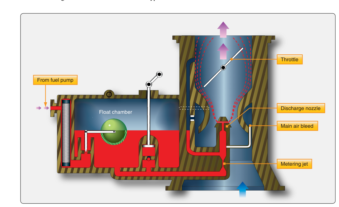
The float-type carburetor is the most common fuel metering device found on light aircraft reciprocating engines, and it remains a foundational topic for any Aviation Maintenance Technician (AMT) seeking a powerplant certificate. Despite the growing prevalence of fuel-injected engines, millions of flight hours are still accumulated each year on carbureted engines, making a thorough understanding of float-type carburetor principles essential for safe maintenance practice and for passing the FAA Powerplant Knowledge Test.
At its heart, the float-type carburetor accomplishes one fundamental job: it meters fuel into the incoming airstream in the correct proportion to support efficient combustion. That proportion — the air-fuel mixture — must be maintained across a wide range of engine speeds and altitudes. The carburetor does this automatically through a clever combination of pressure differentials, mechanical floats, and precisely sized metering orifices, all working together without electronic control.
How the Float-Type Carburetor Works
To understand the float-type carburetor, it helps to think of it in three interconnected systems: the float system, the main metering system, and the throttle system. Each plays a distinct role, and they all interact every second the engine is running.
The Float System
Fuel enters the carburetor from the aircraft fuel system and flows into the float chamber (also called the float bowl). Inside the bowl, a hollow brass or composite float rises and falls with the fuel level. The float is connected mechanically to a needle valve that seats against an inlet fitting. When the fuel level is correct, the float rises enough to push the needle valve closed, stopping fuel flow. As the engine consumes fuel and the level drops, the float descends, the needle valve opens, and more fuel enters. This constant-level regulation is critical because the metering orifices downstream are calibrated to function correctly only when the fuel level in the bowl is at a specific height — typically just slightly below the discharge nozzle opening. If the level is too high, the mixture becomes excessively rich; too low, and the engine runs lean.
The Main Metering System and the Venturi
The main metering system exploits a fundamental principle of fluid dynamics: when a fluid accelerates through a constriction, its static pressure drops. In the carburetor, the constriction is a precisely shaped throat called the venturi (sometimes called the venturi tube or choke). As intake air rushes through the venturi on its way to the engine cylinders, velocity increases and static pressure falls below atmospheric pressure. This low-pressure region is connected by a passage to the main discharge nozzle, which is immersed in the float chamber fuel.
Because the float chamber is vented to atmospheric pressure (the higher-pressure side), and the discharge nozzle opens into the low-pressure venturi throat, there is a pressure differential across the fuel in the bowl. That differential — the atmospheric pressure pushing down on the bowl fuel versus the sub-atmospheric pressure at the nozzle tip — forces fuel up through the main metering jet and out the discharge nozzle, where it atomizes into the high-velocity airstream. The main metering jet is a precisely sized orifice that controls the volume of fuel flowing into the venturi. The jet size is engineered to produce the desired air-fuel ratio at cruise power settings.
Typical reciprocating aircraft engines are commonly described in FAA powerplant materials as operating around a stoichiometric (chemically ideal) air-fuel ratio of approximately 15:1 by weight, though this is a rounded aviation figure rather than an exact chemical value. In practice, best-power mixtures used for takeoff and climb are typically richer, closer to 12:1–13:1, to provide adequate cooling of combustion chamber components and a safety margin against detonation, while cruise power is often leaned closer to best economy, nearer 15:1. The mixture control, discussed below, allows the pilot and technician to adjust this ratio manually.
The Throttle System
The throttle plate (also called the throttle valve or butterfly valve) is a flat disc mounted on a shaft in the carburetor bore, downstream of the venturi. When the pilot advances the throttle, the plate rotates toward an open position, allowing more air-fuel mixture to flow into the induction system. Closing the throttle restricts flow, reducing engine power. The throttle plate does not directly meter fuel — the venturi and jets handle that — but it changes the volume of charge entering the cylinders, which in turn affects how much vacuum the venturi sees and therefore how much fuel is drawn through the discharge nozzle.
Additional Systems Within the Float-Type Carburetor
Idle System
At low engine speeds (idle), airflow through the venturi is too slow to generate sufficient pressure differential to draw fuel through the main discharge nozzle. To address this, carburetors incorporate an idle circuit. Near the edges of the nearly closed throttle plate, where a localized low-pressure region exists, small idle fuel passages introduce a metered amount of fuel directly. An idle mixture adjustment screw allows the technician to fine-tune the idle fuel flow during maintenance runup. Correct idle mixture adjustment is verified by the classic procedure: with the engine idling smoothly, slowly pulling the mixture control toward IDLE CUTOFF should briefly cause the RPM to rise (indicating the idle mixture was slightly rich) before the engine begins to lose RPM and quit. No RPM rise indicates a lean idle mixture.
Accelerator Pump System
When the throttle is opened rapidly, airflow through the carburetor increases almost instantly, but the heavier fuel momentarily lags behind, causing a transient lean condition that can produce a stumble or hesitation. The accelerator pump compensates by squirting an additional measured shot of fuel into the venturi whenever the throttle is moved quickly toward the open position. The pump is typically a small spring-loaded plunger or diaphragm mechanically linked to the throttle linkage.
Mixture Control System
As an aircraft climbs, air density decreases. Because the venturi responds to the mass differential between air and fuel, a less-dense airflow still draws roughly the same volume of fuel — but with fewer air molecules, the mixture becomes progressively richer at altitude. Uncorrected, this leads to rough running, fouled spark plugs, excessive fuel consumption, and power loss. The mixture control allows the pilot to lean the mixture by restricting fuel flow through a tapered needle or by introducing additional air bleeds into the fuel circuit. In maintenance, the condition of the mixture control mechanism and its ability to achieve complete fuel shutoff (IDLE CUTOFF) is a critical inspection item.
Why It Matters: Safety and Maintenance Implications
From a safety standpoint, the most dangerous phenomenon associated with float-type carburetors is carburetor ice. Because fuel evaporation and the pressure drop in the venturi both cool the incoming air significantly — sometimes by 60°F to 70°F or more — ice can form on the throttle plate and venturi walls even when the outside air temperature is well above freezing. Carburetor heat, which routes air around the exhaust muffler before it enters the carburetor, melts this ice. Technicians must ensure the carburetor heat system is rigged correctly and that alternate air doors seal properly when not in use.
Float-type carburetors are also sensitive to fuel level in the bowl. A worn or punctured float that has taken on fuel will ride lower, causing a chronically rich mixture and high fuel consumption. Conversely, an incorrectly adjusted float that holds the needle valve shut too aggressively can cause fuel starvation. During overhaul, float weight and fuel level are verified against the manufacturer's specifications using a depth gauge or the appropriate fuel level sight glass.
Key Numbers and Rules
- Stoichiometric air-fuel ratio: commonly cited as approximately 15:1 by weight for aviation gasoline as a rounded aviation figure; practical best-power mixtures used for takeoff and climb are typically richer, near 12:1–13:1, while cruise is often leaned closer to best economy, nearer 15:1.
- Float bowl fuel level: must be set to manufacturer specification — typically just below the discharge nozzle lip — to ensure accurate metering.
- Idle mixture check: slow pull of mixture control toward IDLE CUTOFF should produce a brief RPM rise on a correctly adjusted idle circuit; the exact RPM rise is not a fixed FAA figure and is specified by the engine/airframe manufacturer.
- Carburetor icing risk: can occur at outside air temperatures from below freezing up to approximately 100°F (38°C) with sufficient humidity, per FAA carburetor icing probability guidance — most dangerous at partial throttle settings where venturi cooling is most pronounced.
- Accelerator pump purpose: prevents transient lean stumble during rapid throttle advancement by injecting a metered fuel charge mechanically linked to throttle movement.
- Mixture control at altitude: leaning is required as density altitude increases to maintain the correct air-fuel ratio and prevent over-rich operation.
Memory Aid
FIVE-M — the five main systems inside a float-type carburetor:
- Float system — maintains constant fuel level in the bowl
- Idle system — supplies fuel at low airflow/RPM conditions
- Venturi & main metering — creates pressure differential that draws fuel into the airstream
- External mixture control — adjusts air-fuel ratio for altitude and power setting
- Mechanical accelerator pump — prevents lean stumble on rapid throttle opening
Memorizing FIVE-M helps you recall every major sub-system when working through a carburetor troubleshooting scenario on the knowledge test or in the shop.
Common Test Traps
- Confusing venturi pressure with throttle position: The venturi creates the pressure differential that meters fuel — the throttle plate only controls the volume of mixture entering the cylinders. They are separate functions, and test questions sometimes blur this distinction.
- Rich mixture at altitude: Many students assume a fixed carburetor produces a leaner mixture as altitude increases because there is less air. In fact, the mixture becomes richer at altitude because the venturi draws approximately the same fuel volume from a thinner, less-massive airflow.
- Float level and mixture richness: A high float level (fuel too high in the bowl) means a richer mixture; a low float level means a leaner mixture. Test questions often reverse these, so keep the relationship clear: higher fuel level = shorter distance fuel must be lifted = more fuel delivered = richer mixture.
- Idle mixture adjustment direction: Turning the idle mixture screw in (clockwise) on most designs leans the idle mixture; turning it out (counterclockwise) richens it. However, always defer to the specific engine manufacturer's instructions, because some designs are opposite — the test may present a scenario where direction matters.
- Carburetor ice identification: Ice in the carburetor causes a gradual, unexplained RPM drop (fixed-pitch prop) or manifold pressure drop (constant-speed prop) without any change in throttle position. Students sometimes confuse this with a magneto drop or fuel contamination.