Every reciprocating aircraft engine needs a reliable way to mix fuel and air in the correct proportions before combustion. For decades, the float-type carburetor was the dominant solution, but fuel injection systems have become increasingly common in general aviation and are now standard on many modern aircraft engines. For the Aviation Maintenance Technician (AMT) working on powerplant systems, understanding the design, operation, advantages, and shortcomings of each system is essential — both for the FAA Knowledge Test and for real-world airworthiness decisions.
This article compares carburetor and fuel injection systems side by side, covering how each meters fuel, why engineers and operators choose one over the other, the key testable specifications, and the failure modes you must recognize on the bench and in the field.
How the Carburetor System Works
The float-type carburetor operates on the Venturi principle. As intake air accelerates through the narrowed venturi throat, its pressure drops below atmospheric. This low-pressure zone draws fuel from a float bowl maintained at a relatively constant level by a needle valve and float assembly. The fuel mixes with the airstream in the carburetor throat and travels as a fuel-air charge through the intake manifold to all cylinders simultaneously.
Fuel metering is controlled primarily by the main metering jet (a fixed orifice) and the mixture control, which either adjusts a needle or bleeds additional air into the fuel circuit. Idle systems, accelerating wells, economizer circuits, and power enrichment systems add complexity that allows the carburetor to approximate the correct mixture across a range of power settings and altitudes. However, because fuel is introduced upstream of the cylinders, the mixture charge must travel varying distances through the manifold, which can result in uneven fuel distribution among cylinders.
The Icing Problem
The most operationally significant disadvantage of the carburetor is its susceptibility to carburetor ice. As fuel vaporizes in the venturi, it absorbs heat (latent heat of vaporization), and the Venturi effect itself causes a further pressure and temperature drop. This combination can reduce carburetor throat temperature by as much as 60 to 70 degrees Fahrenheit below the ambient air temperature, even on a relatively warm day. Ice can form on the throttle plate and venturi walls at ambient temperatures as high as 70°F (21°C) with high relative humidity, partially or completely blocking airflow. The FAA Aviation Maintenance Handbook (FAA-H-8083-32) and the Pilot's Handbook of Aeronautical Knowledge (FAA-H-8083-25) both address this hazard. Carburetor heat systems route exhaust-heated air to the carburetor air inlet to melt accumulated ice, but doing so reduces engine power and introduces less dense air, which enriches the mixture.
How the Fuel Injection System Works
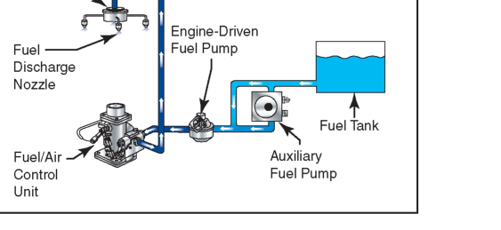
A continuous-flow fuel injection system — the most common type on general aviation reciprocating engines — does not rely on a venturi to draw fuel. Instead, an engine-driven fuel pump supplies fuel under pressure to a flow divider (also called a fuel manifold valve), which distributes metered fuel to individual injector nozzles at each cylinder intake port. The fuel injector nozzle discharges fuel directly into the intake port, where it mixes with incoming air just before entering the cylinder.
Fuel metering is accomplished by the fuel-air control unit (also called the fuel control unit or throttle body), which incorporates a throttle valve to control airflow and a metering valve to proportion fuel flow relative to that airflow. The metered fuel pressure differential across the injector nozzles determines fuel flow, and the mixture control adjusts the metering valve to lean or enrich the mixture. Because each cylinder receives fuel independently from the flow divider, distribution is far more uniform than in a carburetor system.
Direct Cylinder Port Injection vs. Throttle Body Injection
In the continuous-flow system common to Lycoming and Continental engines, fuel is injected at the intake port rather than directly into the cylinder (that would be true direct injection). The port injection location means fuel never sits in the intake manifold as liquid, greatly reducing the icing hazard. Throttle body injection, used on some larger radial and turbine-adjacent designs, introduces fuel downstream of the throttle plate but upstream of the intake runner; it is less common and offers intermediate distribution quality.
Side-by-Side Comparison: Advantages and Disadvantages
Understanding where each system excels and where it struggles is the heart of this topic for the AMT Knowledge Test.
Carburetor advantages: The carburetor system is mechanically simpler, has fewer components, and is generally less expensive to overhaul. It is self-priming at start — fuel is already in the intake path — and functions without an auxiliary fuel pump in most installations (though a boost pump is usually fitted for safety). Troubleshooting is more straightforward, and the system is proven over many decades of operation.
Carburetor disadvantages: Susceptibility to carburetor ice is the foremost operational hazard. Uneven fuel distribution across cylinders leads to power variations and can contribute to detonation in the richest cylinder. The system is more sensitive to attitude changes that affect float level (though this is largely mitigated in aerobatic carburetors). Fuel economy is generally poorer than injection due to the need to run richer-than-stoichiometric mixtures to protect all cylinders.
Fuel injection advantages: Fuel injection eliminates the venturi-related temperature drop, making induction icing far less likely (though throttle body icing at the air inlet can still occur in certain conditions). Uniform fuel delivery to each cylinder improves combustion efficiency, allows leaner cruise operation, and reduces the risk of detonation in any single cylinder. Throttle response is more immediate, and the system is better suited to inverted or unusual-attitude flight. Fuel injection also integrates more naturally with modern engine monitoring systems that can display individual cylinder fuel flow and exhaust gas temperatures.
Fuel injection disadvantages: Hot-start difficulties are a well-known characteristic. When a hot engine is shut down and then immediately restarted, residual heat vaporizes fuel in the lines, causing vapor lock that makes the engine reluctant to restart. Technicians must follow specific hot-start procedures. Fuel injection systems have more components — the engine-driven pump, auxiliary pump, fuel-air control unit, flow divider, and individual injectors — increasing the potential points of failure and raising overhaul cost and complexity. Clogged injector nozzles cause uneven fuel flow and rough engine operation; nozzles must be cleaned at regular inspection intervals. The system also requires an auxiliary (boost) pump for starting and as a backup if the engine-driven pump fails.
Key Numbers and Rules
- Injector nozzle cleaning: Fuel injector nozzles should be inspected and cleaned at every 100-hour or annual inspection per the engine manufacturer's maintenance manual; clogging is the most common injector fault.
- Carburetor icing temperature range: Icing is most likely at ambient temperatures between approximately 20°F and 70°F (-7°C to 21°C) with high relative humidity; serious icing can occur at temperatures above freezing.
- Fuel pump redundancy: Fuel injection systems require an electrically driven auxiliary boost pump to supply fuel during start and as backup for the engine-driven pump; this is a required airworthiness item per the aircraft's type certificate data sheet.
- Mixture distribution: Carburetors serve all cylinders from a single mixture point; injectors meter each cylinder individually, which is why injected engines typically show tighter cylinder-to-cylinder EGT spreads.
- Vapor lock susceptibility: Fuel injection systems are more vulnerable to vapor lock than carburetors because fuel lines near the engine are exposed to greater heat soak after shutdown.
- Flow divider function: The flow divider (manifold valve) equalizes fuel pressure to all injector lines and closes when the engine is shut down to prevent fuel dribble from the nozzles, which would cause hard starting.
Why It Matters: Safety and Maintenance Implications
For the AMT, knowing which system is installed and its specific failure modes is not just a test requirement — it directly affects airworthiness decisions. A carburetor with a deteriorated float will allow the bowl to overfill, producing an excessively rich mixture and potential fuel overflow into the intake. A cracked carburetor body can cause an air leak that leans the mixture dangerously. On the injection side, a partially clogged nozzle will lean one cylinder while leaving others at the intended mixture, potentially causing preignition or detonation in the affected cylinder without an obvious cockpit indication unless a multi-probe EGT system is installed.
Technicians must also understand that removing, cleaning, and reinstalling fuel injection nozzles requires care to avoid cross-threading the soft brass fittings and to verify that the correct nozzle size (color-coded by flow rate) is reinstalled in the correct cylinder position, as manufacturers sometimes specify different nozzle sizes for different cylinder locations to fine-tune distribution.
Common Test Traps
- Icing on injected engines: Many students assume fuel injection eliminates all icing risk. It eliminates carburetor-venturi ice but not impact ice at the air inlet filter or throttle body ice. Expect questions that distinguish between these ice types.
- Hot-start difficulty as a defect: Test questions sometimes describe a hot-start difficulty on an injected engine and ask for the cause. This is a normal characteristic of continuous-flow injection due to vapor lock, not a mechanical defect, though verifying proper fuel pressure and boost pump operation is always appropriate.
- Float-bowl icing vs. venturi icing: Float-bowl icing (impact ice at the inlet) is different from throttle-plate ice caused by fuel vaporization. Both can occur in a carburetor system; the distinction matters for both the test and real diagnosis.
- Flow divider vs. fuel nozzle: The flow divider distributes fuel to the nozzle lines but does not meter individual cylinder flow — metering occurs at the fuel-air control unit. The nozzles are fixed orifices that create the final pressure drop delivering fuel to the port.
- Mixture control operation: On a carburetor, pulling the mixture to idle cutoff stops fuel flow at the idle cutoff valve; on many injection systems, moving the mixture to cutoff closes the metering valve in the fuel-air control unit. Both accomplish engine shutdown, but the mechanical path is different — a test may ask which component is responsible for fuel shutoff in each system.