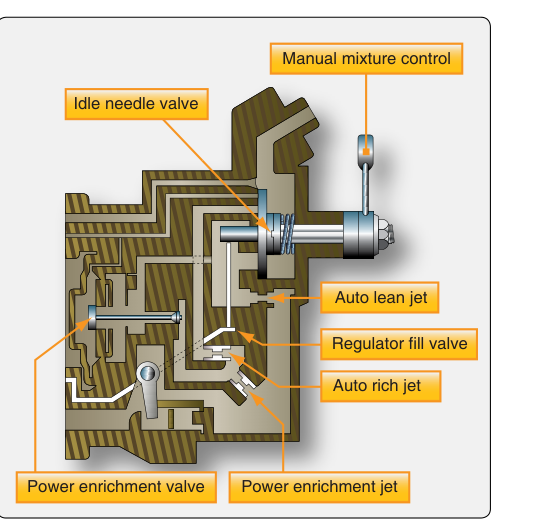
Among the most critical systems an Aviation Maintenance Technician (AMT) must understand is how an aircraft engine measures, controls, and delivers the right amount of fuel at the right time. Two key components sit at the heart of this process: the throttle body and the fuel control unit (FCU). While carbureted engines use a float-type carburetor to perform these functions, modern fuel-injected reciprocating engines and turbine powerplants use dedicated throttle bodies and FCUs that offer superior accuracy, reliability, and performance across a wider range of operating conditions. Mastering the operation of these components is not only essential for passing the FAA AMT Powerplant knowledge and practical tests — it is fundamental to safe engine maintenance and troubleshooting.
This article covers how the throttle body and FCU function individually, how they interact, and what makes them different from carbureted fuel metering systems. It also highlights the most commonly tested concepts on the FAA Powerplant knowledge exam.
The Role of Fuel Metering in Aircraft Engines
Every internal combustion engine requires a carefully controlled ratio of air to fuel. For aviation gasoline (avgas), the stoichiometric ratio — theoretically perfect combustion — is approximately 15:1 by weight (15 pounds of air for every pound of fuel). In practice, aircraft engines operate slightly rich of stoichiometric for cooling and power at full throttle, and lean of stoichiometric for fuel economy at cruise. The fuel metering system's job is to maintain the correct air-fuel ratio across all engine speeds, altitudes, temperatures, and power settings.
The throttle body and FCU divide this task between them. The throttle body is primarily responsible for controlling airflow into the engine, while the FCU schedules the fuel flow to match that airflow. When the two are properly calibrated and working together, the engine receives the right mixture automatically — or nearly automatically, depending on the design.
Throttle Body Operation
The throttle body in a fuel-injected reciprocating engine system functions similarly to the throttle valve in a carburetor, but without the fuel-metering function built into the same housing. Its primary job is to regulate the volume of air flowing into the engine's induction system.
Inside the throttle body, a butterfly valve — a flat, circular disc mounted on a shaft — rotates when the pilot moves the throttle control. When the butterfly is perpendicular to the airflow (closed position), it blocks most air passage, restricting engine power. As the pilot advances the throttle, the butterfly rotates toward a parallel position (wide-open throttle), allowing maximum airflow.
Many throttle bodies used with fuel injection systems also incorporate venturi sections that generate a drop in pressure as air accelerates through the narrowed passage. This pressure differential is sensed by the fuel control unit and used to compute how much fuel to deliver. Some designs also include an impact pressure tube that faces into the incoming airflow and a suction port at the venturi throat. The difference between these two pressures — called metering force — drives fuel through the FCU in proportion to actual airflow, providing an inherently altitude-compensating metering signal.
In some Continental and Lycoming fuel injection systems commonly found on general aviation aircraft, the throttle body, fuel control unit, and mixture control are integrated into a single assembly sometimes called the fuel/air control unit or fuel control assembly. Regardless of the exact configuration, the operating principles remain the same.
Fuel Control Unit (FCU) Operation
The fuel control unit receives fuel from the engine-driven fuel pump at a regulated supply pressure and meters it to the fuel distribution system — typically a flow divider (also called a fuel manifold valve) — which distributes fuel evenly to each cylinder's injector nozzle.
The FCU uses several inputs to compute the correct fuel flow rate:
- Air metering force: The differential pressure signal from the throttle body's venturi tells the FCU how much air the engine is consuming. Greater airflow creates a larger differential pressure, which opens the FCU's fuel metering valve further, increasing fuel flow proportionally.
- Fuel inlet pressure: The FCU references the pressure of fuel entering from the pump to maintain consistent metering regardless of supply pressure fluctuations.
- Mixture control input: A mixture control valve in the FCU allows the pilot to manually adjust the fuel-to-air ratio — enriching the mixture for takeoff or leaning it for cruise and altitude operations. At the full-lean (idle cutoff) position, the mixture valve completely shuts off fuel flow, stopping the engine.
- Altitude compensation (where applicable): Because the pressure differential across the venturi naturally decreases as air density decreases with altitude, the FCU inherently reduces fuel flow as altitude increases, partially compensating for thinner air. This is why fuel-injected engines are said to have automatic mixture compensation, though pilots must still manually lean for best economy at cruise altitudes.
In turbine engines, the FCU (sometimes called the fuel metering unit or, in more modern systems, the hydromechanical metering unit within a FADEC architecture) is considerably more complex. It must schedule fuel flow not only for power setting but also to prevent compressor stall, turbine overtemperature, rich or lean blowout, and over-speed. Turbine FCUs typically sense compressor inlet temperature (CIT), compressor discharge pressure (Pc), engine speed (N1 and/or N2), and power lever angle (PLA) to compute the precise fuel schedule. Modern turbofan engines increasingly use Full Authority Digital Engine Control (FADEC) systems, which replace or supplement hydromechanical FCUs with electronic engine control units, but the underlying metering concepts remain grounded in the same principles.
Flow Divider (Fuel Manifold Valve)
Downstream of the FCU in reciprocating engine fuel injection systems sits the flow divider, a spring-loaded valve that serves two functions: it distributes metered fuel evenly to all cylinder injector nozzles, and it seals off the nozzle lines when the engine is shut down to prevent fuel from dripping into the intake ports and causing a flooded-start or fire hazard. When fuel pressure from the FCU builds above the spring's opening pressure threshold, the flow divider opens and meters fuel simultaneously to all nozzle lines. This equal distribution is critical to uniform cylinder operation and prevention of lean-running cylinders that could lead to detonation.
Why It Matters: Safety and Maintenance Implications
Understanding throttle body and FCU operation guides many critical maintenance and troubleshooting decisions. A clogged or misadjusted fuel injector nozzle can cause one cylinder to run lean while others run rich, producing rough engine operation and the potential for detonation or pre-ignition in the affected cylinder. Differential cylinder head temperature (CHT) readings that are noticeably higher in one cylinder than others often point to a restricted injector nozzle or a flow divider that is not distributing fuel evenly.
Throttle body butterfly shaft wear can create air leaks that unbalance the air-fuel ratio at idle, causing rough idling or an idle mixture that cannot be properly adjusted. Similarly, a leaking throttle body shaft seal can introduce unmetered air, leaning the mixture unexpectedly.
The FCU itself is a precision-machined component with tight tolerances on its metering orifices and valve seats. Contaminated fuel — especially fuel with water or particulate debris — can damage these surfaces and cause inaccurate metering. Maintenance personnel must follow the manufacturer's overhaul and inspection intervals and use only clean, filtered fuel during servicing.
Key Numbers and Rules
- The stoichiometric (chemically perfect) air-fuel ratio for avgas is approximately 15:1 by weight.
- Fuel-injected reciprocating engines typically operate at a rich mixture for takeoff to keep cylinder temperatures low and maximize power.
- Best power mixture is generally slightly richer than stoichiometric; best economy (lean of peak) is slightly leaner than stoichiometric.
- The flow divider opens when metered fuel pressure exceeds its spring-set threshold (typically a few PSI, exact value per manufacturer's data).
- Turbine FCUs schedule fuel using at minimum: power lever position, compressor inlet conditions, and engine speed.
- FADEC systems provide full authority over engine fuel metering through the power lever input, and most implementations use redundant electronic channels rather than a separate mechanical or manual override.
- Idle mixture adjustment on most reciprocating fuel injection systems is made at the FCU idle adjustment screw, with correct idle mixture confirmed by observing a slight RPM rise (typically 25–50 RPM) when the mixture is moved to idle cutoff from an idle power setting.
Common Test Traps
- Throttle body vs. carburetor confusion: The FAA exam may ask what component controls airflow in a fuel-injected engine — the answer is the throttle body, not a carburetor. Carburetors meter both air and fuel in one device; fuel injection systems separate these functions.
- Automatic vs. manual mixture compensation: Students often assume fuel-injected engines require no mixture management. In fact, while the pressure-differential design provides some automatic altitude compensation, pilots must still manually lean the mixture at cruise altitude for best economy or best power.
- Flow divider function: The exam may ask why the flow divider is needed. Its dual role — equal fuel distribution AND nozzle line sealing at shutdown — is frequently tested. Students who only know one function will miss the question.
- FCU vs. fuel pump: The engine-driven pump supplies fuel at an elevated pressure; the FCU meters it. They are separate components with separate functions. Confusing the two leads to errors in troubleshooting questions.
- Idle mixture check procedure: The RPM-rise method (move mixture to cutoff at idle and note the RPM change before the engine quits) is a standard test item. A rise of more than the specified amount indicates the idle mixture is set too rich; no rise or a drop indicates too lean.