Carburetor icing is one of the most insidious threats to a reciprocating aircraft engine. Unlike airframe icing, carb ice can form in ambient temperatures well above freezing — sometimes in conditions as benign as 70°F and high humidity — because the fuel-air mixture in the carburetor venturi undergoes rapid pressure drop and fuel vaporization, which together can drop local temperatures by as much as 70°F. The carburetor heat system exists specifically to counteract this hazard. For the Aviation Maintenance Technician (AMT) working on fuel metering systems, a thorough knowledge of how the carb heat valve is constructed, how warm air is routed, and how the system is maintained is both an exam requirement and a genuine airworthiness responsibility.
This article covers the complete carburetor heat system — from the physics of carb ice formation, through the mechanical design of the heat valve and alternate air source, to maintenance checks and the testable specifics that appear on the FAA AMT Powerplant knowledge test.
Why Carburetor Ice Forms
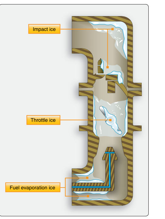
A float-type carburetor meters fuel by drawing it through a main discharge nozzle positioned in the venturi — the narrowest part of the air passage. As air accelerates through the venturi, its pressure drops sharply (Bernoulli's principle), and this pressure drop causes an accompanying temperature drop. Simultaneously, liquid fuel is atomized and vaporized, a phase change that absorbs a significant amount of latent heat from the surrounding air. The combined effect of venturi cooling and fuel vaporization can reduce local mixture temperatures by 40–70°F below ambient. Near the throttle plate, where another restriction exists, temperatures can drop further.
The result is that ice can form on the venturi walls, the throttle plate, and the discharge nozzle even when outside air temperature (OAT) is well above 32°F. The FAA recognizes three types of carburetor ice: fuel evaporation ice, which forms from vaporization cooling; throttle ice, which forms on and just downstream of the partially-closed throttle plate where velocity and pressure effects are greatest; and impact ice, which forms when supercooled water droplets or wet snow strike and freeze on the air intake and carburetor components. The carb heat system directly addresses fuel evaporation ice and throttle ice; impact ice is addressed both by carb heat and by alternate air inlets.
How the Carburetor Heat System Works
The carburetor heat system routes heated air into the engine air induction system, raising the temperature of air entering the carburetor high enough to melt or prevent ice. The heat source is typically the exhaust system — a heat muff (also called a heat exchanger or shroud) surrounds a section of the exhaust pipe or exhaust collector. Ram air from the engine compartment or a dedicated scoop passes over the exterior of the heat muff, picks up heat conducted through the exhaust pipe wall, and becomes the warm air supply. This warm air is ducted to the carburetor heat valve, which is mounted in the induction airbox upstream of the carburetor.
Under normal (carb heat OFF) operation, the valve directs filtered ram air through the normal intake path. When the pilot selects carb heat ON, the valve rotates or slides to block the normal filtered air inlet and open the passage to the heated alternate air supply. The engine now breathes warm, unfiltered air directly from the heat muff ducting. Because this air is warm, it melts existing ice and prevents new ice from forming. It is also less dense than cold outside air, which explains why applying carb heat causes a slight drop in engine power — the pilot and AMT should both expect and understand this normal power reduction.
The Carb Heat Valve — Design and Construction
The carb heat valve (sometimes called the alternate air valve or heat control valve) is the gating component of the entire system. Most designs use a butterfly-style flapper valve mounted in the airbox. A single pivoting gate covers one of two air passages: the outside air passage (normal) and the heated air passage (alternate). In the full COLD position, the gate fully opens the outside air passage and seals the heated air duct. In the full HOT position, it seals the outside air passage and fully opens the heated air duct. The valve should move smoothly to both full stops without binding.
The valve is controlled by a cockpit-mounted knob or lever connected via a push-pull cable or rigid linkage. AMTs must ensure the cable travel provides full actuation in both directions — a common finding during inspection is that cable stretch, fraying, or improper rigging prevents the valve from reaching the full-hot or full-cold stop. Partial application of carb heat is generally discouraged operationally because it can raise carburetor temperature into the range most favorable for ice formation (roughly 32–50°F mixture temperature) without being warm enough to melt ice already present.
The airbox housing is typically aluminum or composite. It must be inspected for cracks, loose rivets, and deteriorated gaskets, since any air leak in the induction system downstream of the throttle represents an unmetered air source that leans the mixture unpredictably. The heat muff itself must be checked for exhaust leaks — any crack in the exhaust pipe inside the heat muff can introduce carbon monoxide (CO) into the induction air, creating a serious crew health hazard. This is a critical inspection point covered in 14 CFR Part 43 maintenance requirements and highlighted in the FAA Airplane Flying Handbook as a cabin air contamination risk.
Heat Source: The Exhaust Heat Muff
The heat muff is a sheet metal shroud, usually stainless steel or aluminized steel, that encases several inches of the exhaust pipe. Ram cooling air enters through openings in the shroud, flows around the hot exhaust pipe, absorbs heat by convection, and exits through the outlet duct leading to the carb heat valve. The exhaust pipe itself never contacts the induction air — the transfer is purely thermal through the pipe wall. This is what makes a cracked exhaust pipe inside the muff so dangerous: combustion gases, rich in CO, can cross directly into the induction air supply.
AMTs inspect heat muffs by removing the shroud and visually inspecting the exhaust pipe for cracks, holes, and distortion. A common technique is to pressurize the exhaust system using a dedicated test kit while watching for smoke or pressure loss, which indicates a breach. The FAA Aviation Maintenance Handbook (FAA-H-8083-32) describes acceptable inspection methods and repair criteria for exhaust system components.
Key Numbers and Rules
- Temperature drop in venturi: Up to 40–70°F below ambient air temperature due to venturi effect and fuel vaporization — carb ice is possible at OATs up to approximately 100°F under humid conditions.
- Three types of carb ice: Fuel evaporation ice, throttle ice, and impact ice — the carb heat system is most effective against the first two types.
- Power drop with carb heat ON: A slight, expected decrease in RPM (in fixed-pitch propeller aircraft) or manifold pressure confirms the system is working; a subsequent RPM rise above the original setting confirms ice was present and has melted.
- Partial carb heat: Operationally discouraged — it can raise the mixture to peak ice-forming temperatures without eliminating ice; AMTs must ensure full valve travel is achievable.
- Heat muff inspection: Exhaust system inspection for cracks inside the muff is a required item on the annual/100-hour inspection checklist under 14 CFR Part 43 Appendix D (as required by 14 CFR 91.409); CO contamination of induction air is an airworthiness hazard.
- Alternate air (injected engines): Fuel-injected engines do not use a carburetor or carb heat but use an alternate air door that opens automatically if the normal filter is blocked by ice — a related but distinct system the AMT must differentiate.
- Control cable rigging: Full travel to both stops is required; rigging specifications are found in the aircraft-specific maintenance manual (AMM) and must be followed precisely.
Why It Matters for AMTs
An improperly maintained carb heat system can fail in ways that are not immediately obvious to the flight crew. A valve stuck in the COLD position provides no protection against ice; a valve stuck in the HOT position robs the engine of power and provides only warm, unfiltered air — accelerating wear if flown in dusty conditions. A cable that appears to move the cockpit control but does not fully actuate the valve gives false assurance. Any exhaust leak inside the heat muff turns a safety system into a source of lethal CO contamination.
These failure modes make carb heat system inspection a genuine airworthiness issue, not a bureaucratic checkbox. AMTs should operationally verify the system during runup checks after maintenance by confirming the RPM drop characteristic of hot air and the return to (or slightly above) normal RPM that indicates ice has been cleared, in addition to the physical and visual inspections described above.
Common Test Traps
- Carb ice temperature range: Many students assume ice only forms at freezing temperatures. The FAA tests the fact that carb ice can form at ambient temperatures up to 70°F or higher with sufficient humidity — do not confuse OAT with mixture temperature inside the venturi.
- RPM behavior with carb heat: A drop in RPM when heat is applied is normal and expected. A rise in RPM after the initial drop confirms ice was present and is melting. A rise above the original RPM is the key confirmation of ice removal.
- Partial heat is dangerous: The FAA tests that partial carb heat can worsen icing by raising temperature into the prime ice-forming zone. Always go full HOT or full COLD.
- Heat source contamination: A cracked exhaust inside the heat muff introduces CO into the induction system — the FAA tests that this is both an engine performance issue and a crew safety hazard.
- Carb heat vs. alternate air (injected engines): The FAA AMT test distinguishes carburetor heat (for float carburetors) from alternate air systems (for fuel-injected engines). Do not conflate the two; injected engines have no carburetor and no carb heat system.