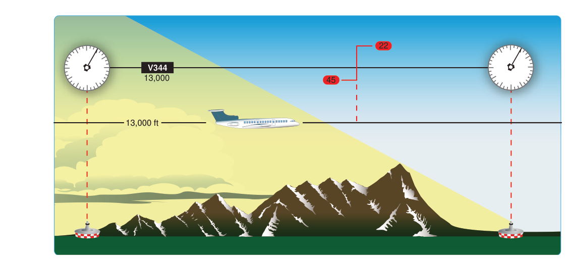
When you fly a Victor Airway — one of the VHF Omni-directional Range (VOR)-based low-altitude airways that crisscross the United States below 18,000 feet MSL — you are not simply pointed at a single station from departure to destination. Instead, the airway is divided into segments, each anchored by a specific ground-based navaid. At some point along each segment, you must switch your navigation reference from the station behind you to the station ahead. That transition point has a formal name: the Changeover Point, or COP.
Understanding COPs is essential for instrument-rated pilots because the FAA knowledge test probes how you interpret en route low-altitude charts, and more importantly, because an error in COP application can lead to undetected course deviation in actual IMC. This article breaks down the concept from first principles, explains the charting conventions, and highlights the exam traps you are most likely to encounter.
What a COP Actually Is
A Changeover Point is the specific location along a Victor Airway segment where a pilot is expected to switch the primary VOR navigation receiver from the behind (or outbound) station to the ahead (or inbound) station. COPs are formally defined and their charting standards described in the FAA Aeronautical Chart User's Guide and the Pilot/Controller Glossary in the Aeronautical Information Manual (AIM); the Instrument Flying Handbook (FAA-H-8083-15) discusses the concept operationally but is not the primary source for the definition. COPs are depicted on en route low-altitude charts published by the FAA's Aeronautical Information Services.
The purpose is straightforward: VOR signals become less reliable at long ranges, especially at low altitudes where terrain, obstacles, and the curvature of the Earth can all degrade signal quality. By switching to the closer, ahead station at the correct geographic point, you ensure that you are always receiving the strongest, most accurate signal available for that portion of the airway. Continuing to navigate from an overly distant station risks Course Deviation Indicator (CDI) fluctuation, false flag indications, or gradual course error — none of which are acceptable in instrument conditions.
How COPs Are Determined and Depicted
In the simplest and most common case, the COP lies at the midpoint between two VOR stations that define an airway segment. This makes intuitive sense: at the midpoint you are equidistant from both stations and therefore receiving signals of roughly equal strength from each. The chart does not need to call special attention to a midpoint COP — it is assumed unless otherwise noted.
However, many airways do not have VOR stations conveniently positioned so that a midpoint COP provides the best signal reception for the entire route. Terrain obstructions, the specific location of an intersecting airway fix, or the need to match a published MEA (Minimum En Route Altitude) may require the COP to be placed off-center. When this happens, the COP is charted with a specific symbol: a zigzag line (resembling a lightning bolt or flag break) placed directly on the airway centerline at the designated transition location, with mileage values shown on each side indicating the distance from the COP to each of the two adjacent VOR stations. For example, you might see “34” on one side of the symbol and “51” on the other, meaning the COP is 34 nautical miles from one station and 51 nautical miles from the other — which figure applies to which station depends on your direction of flight along the airway.
When you see this symbol, it means the authors of the chart have determined that the optimal signal reception handoff point is not at the midpoint. You switch stations at that charted location, not halfway between the two VORs. Missing this distinction is one of the most common errors candidates make on the instrument knowledge test.
How to Apply the COP in Practice
In flight, the procedural application of a COP is simple once you know what to look for:
- Study the chart before departure. During your preflight planning, identify every COP along your route. Note which are standard (midpoint, no symbol shown) and which are non-standard (zigzag symbol with mileage noted).
- Identify the changeover mileage. For non-standard COPs, note the distance from the outbound station at which the switch occurs. Use your DME (if available from the outbound station) or dead-reckoning time/distance to anticipate the transition.
- Tune and identify the new station before reaching the COP. Best practice is to have the ahead station already tuned, identified (listen for the Morse code identifier), and ready in your secondary receiver so you can flip to it immediately at the COP. Do not wait until you are past the point and already losing signal quality.
- Make the switch at or before the COP. Once you cross the COP, the ahead station becomes your primary navigation source. Update your OBS to the inbound radial, verify the CDI response is correct, and confirm no flags.
- Cross-check with other resources. Where GPS is available as a supplemental tool under IFR, it can help you confirm position around the COP, but the VOR remains your primary source on a VOR airway unless your avionics and authorization allow otherwise.
Why COPs Matter for Safety and Compliance
The FAA requires pilots to navigate Victor Airways using approved procedures. Failing to switch at the correct COP is not merely an inconvenience — it can cause a slow, undetected drift off the protected airway corridor. Federal airway protected widths are not a single fixed dimension for every segment; the protected area is defined by primary and secondary obstacle clearance areas that vary with distance from the navaid and route configuration, though a commonly cited primary protected width close to the station is on the order of 4 nautical miles on each side of centerline, widening further from the VOR. That protection is predicated on the assumption that pilots are using the designated navigation source from the correct reference station. A VOR signal received from extreme range may appear valid on the CDI but introduce enough angular error to place the aircraft outside the protected corridor.
In radar-controlled environments, ATC will often catch such deviations, but in areas without radar coverage — and at the lower altitudes where Victor Airways are used — the pilot is the last line of defense. The COP system exists precisely to prevent this class of error, and instrument pilots are expected to follow it as a matter of standard procedure.
Key Numbers and Rules
- Standard COP location: Midpoint between two VOR stations — assumed unless a symbol appears on the chart.
- Non-standard COP: Indicated by a zigzag line on the centerline with nautical-mile distances noted to each adjacent station.
- Victor Airway altitude: As a general rule, Victor Airways extend from 1,200 feet above the surface up to but not including 18,000 feet MSL (Class A airspace begins at 18,000 feet), but the actual floor of any given segment varies and can be higher or lower depending on terrain and the published MEA for that segment.
- Victor Airway width: Not a single fixed dimension; protected airspace is defined by primary and secondary obstacle clearance areas that vary with distance from the navaid, with a commonly cited primary width of about 4 nm on each side of centerline near the station, widening farther out.
- Ahead-station tuning: Best practice is to have the next station tuned and identified before reaching the COP, not after.
- Signal reliability: VOR accuracy and reception degrade with distance and low altitude; the COP is positioned to always keep you within reliable reception of at least one station.
Common Test Traps
- Assuming all COPs are at the midpoint. If the chart shows a zigzag symbol with mileage notations, the COP is explicitly off-center. Read the chart, do not assume halfway. The FAA knowledge test frequently provides an airway segment with a non-standard COP and then asks at what distance from a specific station you should make the switch.
- Confusing the mileage values. The two numbers on a non-standard COP symbol refer to distances to each station, not total segment length. If you see “28” and “47,” the COP is 28 nm from one VOR and 47 nm from the other — do not add them up and divide.
- Switching too late. Waiting until you pass the COP before tuning the next station means you are navigating from a degraded signal. Best practice is to tune and identify the ahead station early so the switchover is seamless.
- Forgetting to update the OBS. After switching to the ahead station, you must set the new inbound course (radial) into the OBS. Failing to do so means the CDI is still referencing the old course, leading to incorrect course guidance even though you are on the right radial.
- Applying IFR en route GPS rules incorrectly. If your GPS is approved for IFR en route navigation, you do not need to switch VOR stations the same way, because GPS determines position independently. However, if the clearance specifies a VOR airway and you are using VOR as the primary means, COP rules apply. Know which navigation mode your clearance and avionics authorize.
Changeover Points are a small but frequently tested detail of en route IFR operations. Mastering them demonstrates that you understand not just the rules of airways navigation, but the underlying reason those rules exist: keeping your navigation reliable, your aircraft on centerline, and your situational awareness sharp in all conditions.