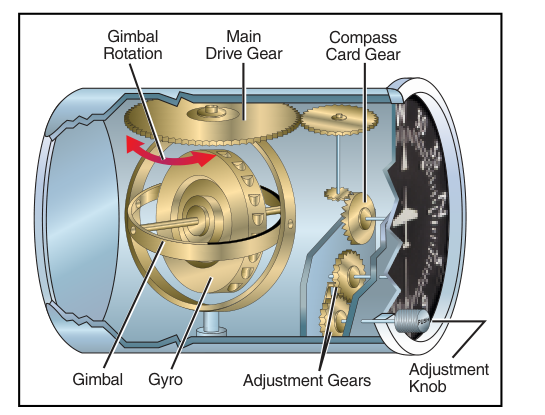
One of the most important instrument cross-checks a private pilot must learn is the relationship between the heading indicator (also called the directional gyro, or DG) and the magnetic compass. Both instruments show the aircraft's heading relative to magnetic north, but they work through entirely different physical principles — and each has weaknesses the other compensates for. Understanding why these two instruments must work as a team, and how to manage their quirks, is both a safety-critical skill and a popular topic on the FAA Private Pilot Knowledge Test.
At the heart of the matter is a physical phenomenon called gyroscopic precession. The heading indicator relies on a spinning gyroscope to maintain a fixed orientation in space, which makes it a smooth, reliable heading reference in turbulence. But no gyroscope is perfect — bearing friction, mechanical imperfections, and the rotation of the Earth beneath the aircraft all cause the gyroscope's spin axis to slowly wander from its original alignment. Left unchecked, this drift can accumulate to an error of several degrees every few minutes, sending a pilot steadily off course without any obvious indication that something is wrong.
How the Heading Indicator Works
The heading indicator contains a gyroscope whose spin axis is mounted horizontally. Because a gyroscope resists any change to its orientation (a property called rigidity in space), the instrument maintains a fixed directional reference regardless of how the aircraft turns. As the aircraft rotates around the gyroscope, the compass card rotates with the aircraft's case, and the pilot reads whatever heading is displayed on the card under the lubber line.
Most light aircraft use a vacuum-driven heading indicator. Engine-driven vacuum pumps or venturi tubes create suction that spins the gyro rotor through a system of jets. The typical operating vacuum range for these gyroscopic instruments is 4.5 to 5.5 inches of mercury (Hg), which keeps the rotor spinning fast enough for reliable rigidity. Some modern aircraft use electrically-driven gyros, which behave similarly but draw power from the aircraft's electrical bus rather than the vacuum system.
Because the gyroscope is rigid in space — not locked to the Earth — it does not automatically track changes in magnetic north. The pilot must periodically set the instrument manually using the caging and setting knob, aligning the indicated heading with the magnetic compass reading.
What Causes Precession and Drift
The heading indicator drifts due to three overlapping causes:
- Mechanical precession: Friction in the gyro bearings applies a small torque that causes the spin axis to slowly tilt or rotate. This is inherent in any mechanical gyro and cannot be eliminated, only minimized through quality manufacturing.
- Earth rate precession: The Earth rotates approximately 15 degrees per hour. Because the gyroscope remains fixed in space while the Earth (and the aircraft on it) rotates beneath it, even a perfect gyroscope would appear to drift at this rate relative to the Earth's surface. The effect varies with latitude — it is zero at the equator and maximum at the poles.
- Transport wander: As an aircraft flies along a curved path on the Earth's surface (following a great circle route), the gyroscope's reference frame changes slightly relative to local north. This causes an additional slow, predictable drift.
In practice, all three causes combine, and total drift rates for typical light-aircraft vacuum gyros can reach 3 to 5 degrees per 15 minutes, though modern instruments are generally much better than this. Some instrument flying textbooks note an allowable drift of up to 3 degrees per 15 minutes as an airworthiness standard during preflight checks.
The Magnetic Compass: Accurate but Difficult to Read
The magnetic compass requires no power — it is entirely self-contained, using a magnetized card that aligns itself with the Earth's magnetic field. This makes it the ultimate backup and the legal reference for the heading indicator. However, the magnetic compass is notoriously difficult to read accurately in flight because of several errors:
- Oscillation error: In turbulence or normal cockpit vibration, the compass card swings back and forth, making it hard to capture a precise heading.
- Variation: Magnetic north and true north are different everywhere except along the agonic line. Isogonic lines show the amount of variation, and pilots must apply east or west variation corrections when converting between true and magnetic headings.
- Deviation: Electrical equipment, the aircraft's own magnetic fields, and metallic structures deflect the compass slightly from magnetic north. A compass correction card (placard) placed in the cockpit shows the deviation corrections for various headings and must be updated whenever new electrical equipment is installed or the compass is swung.
- Northerly turning error: In the Northern Hemisphere, when turning to or from northerly headings, the compass temporarily leads or lags the actual turn due to the vertical component of the Earth's magnetic field. The compass leads the turn when turning toward the north and lags when turning toward the south. Pilots learn to undershoot (roll out before reaching the desired heading) when turning to north and overshoot (roll out after passing the desired heading) when turning to south to compensate.
- Acceleration/deceleration error: On east or west headings, accelerating causes the compass to show a turn toward north, and decelerating causes it to show a turn toward south. A common memory tool: ANDS — Accelerate North, Decelerate South.
How and When to Align the Heading Indicator
Because the heading indicator drifts and the magnetic compass oscillates, best practice is to cross-check and realign the two instruments approximately every 10 to 15 minutes during straight-and-level, unaccelerated flight. Attempting to read the compass during a turn or acceleration will introduce the errors described above and produce an inaccurate reference heading.
The alignment procedure is simple: ensure the aircraft is in wings-level, coordinated, unaccelerated flight; wait for the compass card to settle; then use the heading indicator's caging/setting knob to match the indicated heading to the compass reading. Do not adjust the heading indicator while turning or climbing, as the gyroscope's rigidity makes the reading unreliable during dynamic maneuvers.
Before any flight, always set the heading indicator on the ground after engine start (so the gyro has time to spin up) and before taxiing, aligning it with the known runway heading or a magnetic compass reading taken while the aircraft is stationary. During taxi, observe that the heading indicator responds correctly when turning — it should increase when turning right and decrease when turning left, giving a quick functional check.
Key Numbers and Rules
- Typical heading indicator drift: up to 3 to 5 degrees per 15 minutes for mechanical gyros.
- Realign the heading indicator with the magnetic compass every 10 to 15 minutes in straight, level, unaccelerated flight.
- Vacuum system normal operating range: 4.5 to 5.5 inches Hg.
- Compass deviation corrections are found on the compass correction card (placard) in the cockpit.
- Variation is read from isogonic lines on sectional charts; the agonic line has zero variation.
- Northerly turning error: undershoot the turn (roll out before reaching the heading) when turning to north, overshoot (roll out after passing the heading) when turning to south (in the Northern Hemisphere).
- Acceleration/deceleration error affects compass reading primarily on east/west headings.
Memory Aid
ANDS — the standard mnemonic for magnetic compass acceleration error:
- Accelerate — compass swings toward North
- Decelerate — compass swings toward South
This applies when flying on an east or west heading. On north or south headings, acceleration/deceleration error is negligible. Remember ANDS and you will never confuse which direction the compass lies when you push in or pull back on the throttle.
Common Test Traps
- Confusing rigidity and precession: Rigidity in space is the property that makes gyros useful as attitude references; precession (drift) is the unwanted consequence of imperfect rigidity. The FAA may describe each and ask you to name the correct property.
- Forgetting when to align: The heading indicator must be set during straight, level, unaccelerated flight. Students sometimes think they can align it in a climb or during a turn — the oscillating compass reading would give a false reference.
- Northerly turning error direction: Many students mix up which way the compass leads or lags. Remember: in the Northern Hemisphere, the compass leads the turn (shows more turn than has actually occurred) when approaching a heading of north, and lags the turn (shows less turn than has actually occurred) when approaching a heading of south.
- Treating ANDS as applying on all headings: Acceleration error is greatest on east/west headings and nearly zero on north/south headings. The FAA test frequently specifies an east or west heading in questions about this error.
- Assuming a drifting heading indicator is broken: Some drift is normal and expected. A drift rate within 3 degrees per 15 minutes is acceptable. A heading indicator that drifts dramatically faster, or one that tumbles, may indicate a vacuum system failure — check the vacuum gauge immediately.