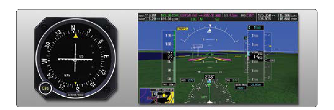
The Instrument Landing System (ILS) is the gold standard for precision approaches, guiding aircraft along both a horizontal and vertical path to the runway. While the localizer keeps you laterally aligned, the glideslope provides the critical vertical guidance — typically a 3-degree descent path that takes you from the final approach fix all the way to a point just above the touchdown zone. For instrument rating candidates, understanding not just how to follow the glideslope needle but why it behaves the way it does is the difference between a smooth, professional approach and an unstabilized nightmare. This article covers the full lifecycle of a glideslope intercept: setup, interception, tracking, corrections, and the traps that catch unprepared pilots.
The ILS glideslope transmitter sits beside the runway, offset from the centerline, and broadcasts a UHF signal (329.15–335.00 MHz) that is automatically paired when you tune the localizer frequency on your NAV radio. The glideslope signal creates two overlapping lobes — a narrower upper lobe and a lower one — with the on-path signal at the intersection. Full-scale deflection on the glideslope indicator is only ±0.7 degrees, which translates to roughly 50 feet above or below the glidepath at the outer marker. This extreme sensitivity is intentional: it gives you the precision needed for low-visibility operations, but it demands disciplined technique.
Setting Up for the Approach
A successful glideslope intercept begins well before you reach the final approach fix. Fly the published procedure turn or radar vectors to ensure you are configured, stabilized, and level at the appropriate glideslope intercept altitude before the needle comes alive. Reference your approach chart: the glideslope intercept altitude is the altitude at which you should be established in level flight, awaiting the glideslope to descend to you from above. This is a crucial concept — you should always intercept the glideslope from below. Intercepting from above puts you on a false glideslope (ILS glideslopes have multiple false courses above the true path) and can result in a dangerously steep descent.
Before reaching the final approach course, complete the following: tune and identify the ILS frequency (listen for the Morse code identifier), brief the approach plate (decision altitude, missed approach point, missed approach procedure, minimums), set your altimeter with the current setting, configure the aircraft for approach speed and configuration appropriate for your aircraft type, and confirm the course is set in your HSI or OBS. The Instrument Flying Handbook (FAA-H-8083-15) emphasizes that a stabilized approach begins with a stabilized setup — rushing the cockpit preparation directly contributes to deviation during the approach.
Intercepting the Glideslope
As you fly the final approach course at your intercept altitude, watch the glideslope indicator (the horizontal needle on your CDI or the glideslope pointer on your HSI). When the needle is at full-scale deflection above center, the glideslope is above you. As it begins to move downward — typically called "coming alive" — you are approaching the glidepath from below. Standard practice is to begin your descent when the needle reaches approximately one dot above center (one quarter of full scale), not when it reaches center. This anticipation prevents you from busting through the glidepath on the initial descent.
The rate of descent needed to track the glideslope is a function of your groundspeed. A widely used rule of thumb is to multiply your groundspeed by 5 to get the approximate feet-per-minute descent rate for a 3-degree glideslope. For example, at 90 knots groundspeed: 90 × 5 = 450 feet per minute. At 120 knots: 120 × 5 = 600 fpm. This gives you a starting power/pitch reference so the needle does not have to do all the work of finding the right descent rate.
Tracking the Glideslope
Once established on the glideslope, the fundamental technique is to make small, coordinated adjustments to pitch and power simultaneously. On the glideslope, pitch primarily controls your position on the path (up or down), while power primarily controls your airspeed and energy state — though in practice these are interconnected. The Instrument Flying Handbook describes the control priority as: pitch to maintain airspeed on a stabilized approach, and power to maintain the glidepath. Either philosophy can work if applied consistently, but what never works is large, abrupt corrections.
When the glideslope needle deflects upward (you are below the glidepath), reduce your rate of descent by slightly increasing pitch and/or adding a small increment of power. When the needle deflects downward (you are above the glidepath), increase your descent rate by slightly reducing pitch and/or reducing power. The key word is slightly. Because full-scale deflection is only 0.7 degrees, a correction that feels significant in terms of pitch input can easily overshoot the centerline. Apply the correction, wait for the needle to respond (there is a slight lag), and then return to a close approximation of your baseline pitch and power as the needle returns to center.
Use the trend of the needle, not just its position. If the needle is one dot low but moving upward, your correction is working — don't add more input. If the needle is on center but drifting downward, begin a gentle correction before it deviates further. This predictive technique — sometimes called "flying ahead of the needle" — is what separates proficient instrument pilots from those who constantly chase the instruments.
Wind Effects and Crosswind Corrections
Wind affects glideslope tracking in two important ways. First, a headwind reduces groundspeed, which lowers the required descent rate; a tailwind increases groundspeed and thus requires a higher descent rate. Always recalculate your expected descent rate if the winds aloft differ significantly from the surface winds. Second, a crosswind will push you off the localizer, and as you correct laterally, your glideslope tracking can be disrupted if you allow the aircraft to bank significantly and alter your energy state. Maintain heading corrections for crosswind using crab angle on the localizer; keeping coordinated and wings-level-ish protects glideslope stability.
Key Numbers and Rules
- Glideslope angle: Typically 3 degrees (check the approach chart; some ILS approaches have slightly steeper angles).
- Full-scale deflection: ±0.7 degrees, approximately 50 feet at the outer marker.
- Glideslope frequency: UHF 329.15–335.00 MHz, automatically paired with the localizer VHF frequency.
- Descent rate rule of thumb: Groundspeed × 5 = approximate fpm for a 3-degree glideslope.
- Intercept from below: Always. Intercepting from above risks a false glideslope and is a common checkride failure point.
- Decision Altitude (DA): The altitude at which you must decide to land or execute the missed approach. For a standard Category I ILS, DA is typically 200 feet above touchdown zone elevation, with visibility of ½ statute mile (or RVR 2400).
- Glideslope out: If the glideslope fails during an approach, the ILS immediately becomes a non-precision localizer approach. Published LOC minimums (higher than ILS minimums) apply.
- Approach categories: Your aircraft approach category (A, B, C, D) is determined by 1.3 times the stall speed in the landing configuration (Vso). This determines which minimums column to reference on the approach plate.
Memory Aid
Use the phrase "MARTHA" to remember the elements of a complete ILS approach setup:
- M — Markers/Minimums (note DA, missed approach point)
- A — Altimeter (set current altimeter setting)
- R — Radios/Receivers (tune, identify, and confirm the ILS)
- T — Time (note timing requirements if applicable)
- H — Heading (set inbound course in OBS/HSI)
- A — Airspeed/Aircraft configuration (flaps, gear, approach speed)
Running MARTHA during vectors or the procedure turn ensures nothing critical is missed before the needle comes alive.
Why It Matters
The glideslope is not merely a convenience — in low-IMC conditions it is often the only thing standing between a controlled approach and controlled flight into terrain. Glideslope deviations that seem minor at the outer marker become significant at the middle marker, and catastrophic near the threshold. The FAA defines a stabilized approach as one in which, by 1,000 feet AGL in IMC (500 feet AGL in VMC), the aircraft is on the correct flight path, at the correct speed, in the correct configuration, with a stable power setting. An approach that is not stabilized by those gates should be abandoned in favor of the missed approach — this expectation is part of every practical test standard for the instrument rating.
Common Test Traps
- False glideslope confusion: The ILS generates false glideslopes at approximately 9, 12, and 15 degrees above horizontal. Always intercept from below and from the published intercept altitude to avoid these false paths, which present as a normal needle but at a dangerously steep angle.
- Glideslope sensitivity misunderstanding: Students often confuse glideslope and localizer sensitivity. The glideslope is far more sensitive (±0.7°) than the localizer (±2.5° at the threshold). Large corrections appropriate for localizer tracking will massively overshoot the glideslope.
- Forgetting the "from below" rule: On written and oral exams, questions about descending through the glideslope intercept altitude before the needle is centered test whether you understand the false glideslope risk.
- Confusing DA with MDA: The ILS uses a Decision Altitude (DA), not a Minimum Descent Altitude (MDA). At DA you must immediately initiate a missed approach if required visual references are not in sight — you do not "level off and wait."
- Glideslope inoperative minima: If the glideslope receiver fails or the ground station is NOTAMed out, the approach reverts to a localizer (LOC) approach with non-precision (MDA-based) minimums. Failing to apply the correct minimums in this scenario is a common checkride and written test error.