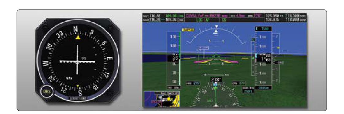
The Instrument Landing System (ILS) is the most precise and widely used ground-based approach aid in the United States. It gives pilots two independent radio signals — one guiding them left and right toward the runway centerline, and one guiding them up or down along a safe descent angle. Understanding exactly how each signal is generated, how it is displayed in the cockpit, and what the deflections mean is essential for flying a stabilized, accurate ILS approach — and for passing the FAA Instrument Rating knowledge test.
Both signals are transmitted continuously from antennas on the airport surface. The pilot's receiver interprets the signals and drives a Course Deviation Indicator (CDI) needle (or flight director bars) to show where the aircraft is relative to the ideal path. The goal is always the same: keep the needles centered and you are precisely on course and on the correct vertical path to the touchdown zone.
The Localizer: Lateral Guidance to the Runway
The localizer antenna array is positioned beyond the departure end of the runway, transmitting two overlapping lobes on a frequency between 108.10 MHz and 111.95 MHz (all on odd tenths). The left lobe is modulated at 90 Hz and the right lobe at 150 Hz. The receiver computes the difference in modulation depth between the two signals. When the difference is zero, the aircraft is on the extended centerline of the runway — the localizer course. Any deviation from centerline causes one modulation to dominate, driving the CDI needle left or right to indicate the direction the pilot must fly to return to center.
A critical characteristic of the localizer is its sensitivity: the course is adjusted so that full-scale deflection corresponds to a 700-foot linear width at the runway threshold, not a fixed angular value. Because that linear width is held constant while runway lengths and antenna-to-threshold distances vary, the actual angular width of full-scale deflection varies by installation, typically totaling somewhere in the range of about 3° to 6°, rather than a single universal ±2.5° figure. This is far more sensitive than a VOR, where full-scale deflection is ±10°. Because the localizer beam narrows as the aircraft approaches the antenna, needle movements become increasingly sensitive the closer the aircraft gets to the runway. A half-dot deflection at 5 miles represents a much larger off-course error than a half-dot at 1 mile. Students often underestimate how quickly small heading corrections must be made on short final.
The localizer also broadcasts an identifier in Morse code — typically a three-letter code beginning with the letter I (for example, I-ORD). Pilots must positively identify the localizer before relying on it for navigation. If the identifier is absent or irregular, the signal is unreliable and the approach must not be flown.
The Glide Slope: Vertical Guidance Down the Approach Path
The glide slope antenna is located approximately 750 to 1,250 feet from the runway threshold, offset to one side of the runway. It transmits on a paired UHF frequency between 329.15 MHz and 335.00 MHz — paired automatically when the pilot tunes the localizer frequency. The pilot never tunes the glide slope frequency separately; it is always paired to the localizer channel.
Like the localizer, the glide slope uses two overlapping lobes modulated at 90 Hz and 150 Hz, but oriented vertically. The upper lobe is the 90 Hz signal and the lower lobe is the 150 Hz signal. When the 90 Hz signal dominates, the aircraft is above the glide path and the needle deflects downward (fly down, toward the needle). When the 150 Hz signal dominates, the aircraft is below the glide path and the needle deflects upward (fly up, toward the needle). Again, keep the needle centered and you are on the correct path.
The standard glide slope angle is 3°, although some airports use slightly steeper angles (typically up to 4°) to clear obstacles. A 3° glide slope produces a descent rate of approximately 300 feet per nautical mile, or roughly 500–600 feet per minute at a typical approach speed of 90–120 knots. A useful rule of thumb: multiply groundspeed (knots) by 5 to get the approximate descent rate in feet per minute required to stay on a 3° glide slope. For example, at 90 knots: 90 × 5 = 450 fpm.
Glide slope sensitivity is even more pronounced than localizer sensitivity. Full-scale deflection on the glide slope is approximately ±0.7°, which corresponds to only about ±75 feet at the outer marker and narrows significantly closer in. Pilots should never chase the needle aggressively; small, smooth control inputs and power adjustments are the hallmark of a stabilized ILS approach.
False Glide Slopes
One of the most important — and most tested — aspects of the ILS glide slope is the existence of false glide slopes. The glide slope antenna produces multiple usable signal lobes above the primary 3° path. False glide slopes can appear at roughly 6°, 9°, and 12° above the horizon. If a pilot intercepts the beam from above and captures one of these false lobes, the CDI will appear to be centered, but the aircraft is actually at an incorrect and dangerously steep angle.
The standard protection against false glide slopes is to always intercept the glide slope from below. When flying the ILS, the glide slope needle should be above center (indicating the aircraft is below the beam) as the aircraft approaches the final approach fix. As altitude is reduced to match the approach, the needle descends toward center. This procedure ensures the aircraft captures the correct 3° lobe rather than a false one above it.
Why It Matters: Decision Altitude and Visibility
A full ILS (Category I) approach has a Decision Altitude (DA) — formerly called Decision Height (DH) — of at least 200 feet above the touchdown zone elevation, with a visibility requirement typically of at least ½ statute mile (or 1,800 feet Runway Visual Range). At DA, the pilot must have the required visual references to continue the approach; otherwise, an immediate missed approach must be executed.
The precision of the ILS — delivering lateral and vertical guidance simultaneously — is what makes this low DA possible. Non-precision approaches (which have no glide slope) require significantly higher Minimum Descent Altitudes (MDAs) because terrain and obstacle clearance must be managed with greater margins when vertical guidance is absent. Understanding the ILS allows pilots to take full advantage of the lowest legal minimums available on a given approach plate.
Key Numbers and Rules
- Localizer frequency range: 108.10–111.95 MHz, odd tenths only
- Localizer full-scale deflection: defined by a 700-foot linear width at the runway threshold, not a fixed angle — actual angular width varies (typically about 3° to 6° total) by runway length and antenna distance
- Glide slope pairing: UHF 329.15–335.00 MHz, automatically paired — never manually tuned
- Standard glide slope angle: 3° (some approaches up to 4°)
- Glide slope full-scale deflection: approximately ±0.7°
- Rate of descent rule of thumb: groundspeed (knots) × 5 = approximate fpm for 3° glide slope
- CAT I ILS minimums: DA of at least 200 feet AGL, visibility at least ½ SM (or 1,800 RVR)
- Localizer identifier: always begins with the letter I; must be positively identified before use
- False glide slopes: exist at approximately 6°, 9°, and 12°; always intercept from below
- Localizer usable range: 18 NM within ±10° of centerline; 10 NM between ±10° and ±35°
Common Test Traps
- Glide slope needle direction vs. correction direction: A needle deflected downward means you are below the glide path — fly up, toward the needle. Students sometimes reverse the correction, especially under pressure. Remember: fly toward the needle, just as with the localizer.
- Localizer sensitivity vs. VOR sensitivity: Many students forget that a localizer is considerably more sensitive than a standard VOR. The same physical needle deflection on an ILS represents a much smaller course error. Overcorrecting is a very common and very testable error.
- Manually tuning the glide slope: The glide slope is always paired automatically when you tune the localizer. There is no separate glide slope frequency to tune. Any question suggesting otherwise is a trap.
- Intercepting the glide slope from above: Intercepting from above risks capturing a false glide slope. The approach must be flown so that the glide slope is captured from below — the correct 3° lobe, not a steeper false one.
- Decision Altitude vs. Minimum Descent Altitude: Precision approaches (ILS) use a DA — a point in space where a go/no-go decision is made. Non-precision approaches use an MDA — a floor that may not be descended below until required visual references are in sight. Confusing these two on the written test is extremely common.