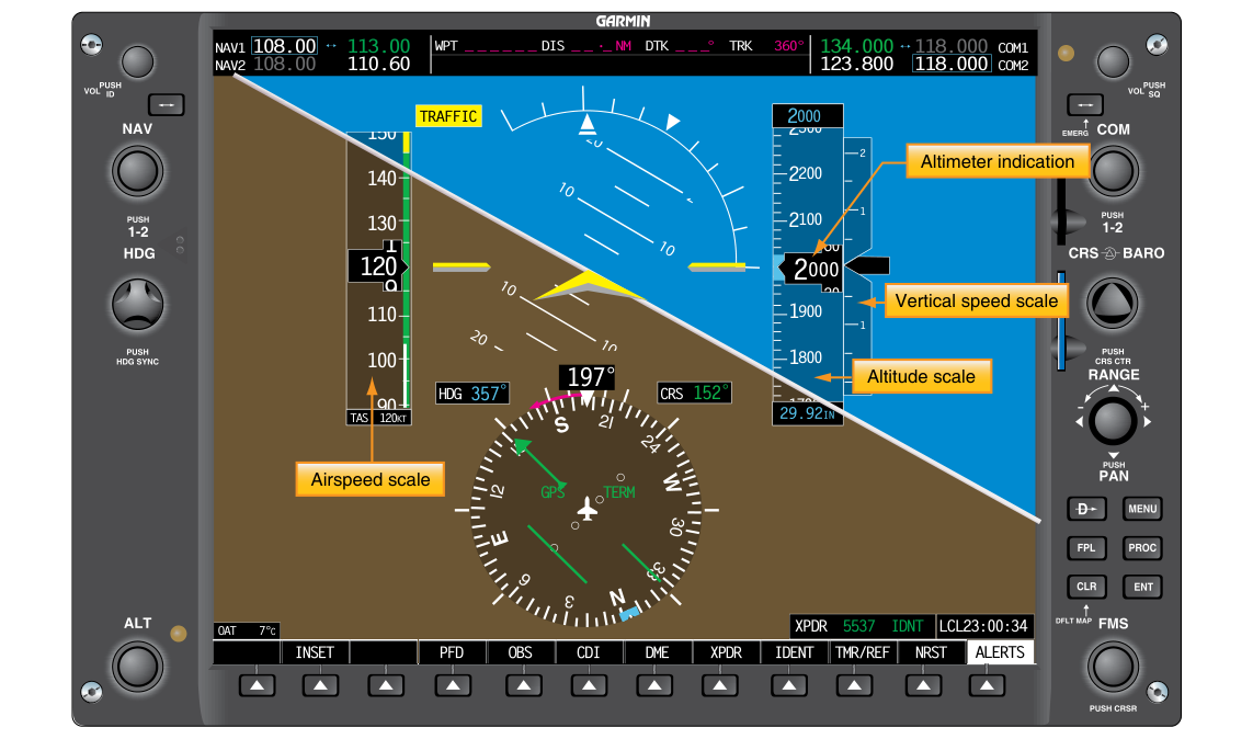
Glass cockpit avionics have replaced the traditional "six-pack" of analog gauges in most modern certificated aircraft, consolidating attitude, airspeed, altitude, heading, vertical speed, and navigation data onto one or more large liquid-crystal Primary Flight Displays (PFDs). While this integration dramatically improves situational awareness and reduces pilot workload, it also introduces a new class of risk: if a single display or its driving computer fails, the crew could theoretically lose all of that information simultaneously. To prevent that outcome, the FAA and the broader regulatory framework — including 14 CFR Part 23 and Part 25 certification standards, AC 25.1309 system design concepts, and the guidance in FAA Advisory Circular AC 23.1311 — require that integrated avionics systems be designed with multiple, independent layers of redundancy. For airframe technicians, understanding how that redundancy is architected, installed, and verified is essential to maintaining the airworthiness of glass-cockpit aircraft.
This article walks through the core redundancy requirements, the typical hardware architecture used to meet them, the inspection and maintenance implications for AMT Airframe candidates, and the most commonly tested knowledge points related to these systems.
The Regulatory Foundation
Certification requirements for electronic display systems flow primarily from 14 CFR Part 23 (normal-category aircraft) and 14 CFR Part 25 (transport-category aircraft). Both parts require that each required flight instrument be reliably available to the flight crew. For integrated display systems, the key regulatory concept is that no single failure — whether of a sensor, a line-replaceable unit (LRU), a power bus, or a display itself — should cause the loss of all required flight instrument information. This principle is formally called single-failure tolerance.
Under 14 CFR § 23.1311 (electronic display instrument systems), the avionics suite must be designed so that a display failure is immediately obvious to the flight crew and that backup information remains available. Similarly, 14 CFR § 25.1309 establishes a probability-based safety standard: catastrophic failure conditions must be extremely improbable (less than 10⁻⁹ per flight hour), while hazardous conditions must be extremely remote (less than 10⁻⁷ per flight hour). Because total loss of attitude and airspeed information in IMC would be classified as hazardous or catastrophic, the system must be architecturally structured so the probability of that combined loss meets those thresholds.
How PFD Redundancy Is Architected
Manufacturers achieve single-failure tolerance through several layered strategies. Understanding each layer is important for an AMT because each layer represents a separate line item on an inspection or troubleshooting checklist.
Dual or Triple Air Data and Attitude Heading Reference Systems
The most fundamental layer of redundancy is multiple independent sensor systems. Nearly every FAA-certificated glass cockpit uses at least two fully independent Air Data Computers (ADCs) and two independent Attitude and Heading Reference Systems (AHRS). Some transport-category aircraft use three of each. Each ADC processes pitot-static inputs — total pressure, static pressure, and outside air temperature — to compute indicated airspeed, pressure altitude, and vertical speed. Each AHRS uses a combination of solid-state gyroscopes, accelerometers, and magnetometers to compute pitch, roll, and magnetic heading.
Because these units are physically separate and draw from separate pitot-static ports (or at minimum separate plumbing branches), a blockage, leak, or electrical failure affecting one ADC will not affect the other. During maintenance, it is critical to verify that each ADC's pitot-static connections are routed correctly and that there is no cross-contamination between the two systems. After any pitot-static work, both systems must be leak-tested in accordance with 14 CFR § 91.411 and the aircraft manufacturer's maintenance manual.
Independent Power Buses
A display that is technically functional but deprived of electrical power provides no value. Accordingly, PFD systems are wired so that critical avionics draw from at least two independent electrical buses — typically the main avionics bus and an essential (emergency) avionics bus. The essential bus is designed to remain powered even during partial electrical failures, often protected by a dedicated circuit breaker and sometimes connected directly to the battery or a separate battery bus. Technicians must verify bus assignments against the aircraft wiring diagram and ensure circuit breakers are correctly rated and not subject to nuisance tripping.
Reversionary Display Modes
Most integrated glass cockpit systems include a reversionary mode — sometimes called a composite mode — that can be activated automatically or manually when a display fails. In reversionary mode, the surviving display(s) reconfigure to present the most critical information from both the failed and surviving channels. For example, on a twin-display Garmin G1000 system, if the PFD fails, the Multi-Function Display (MFD) can be switched into reversionary mode to show attitude, airspeed, altitude, and navigation data simultaneously. This is typically activated by a dedicated DISPLAY BACKUP button on the avionics system controller.
From a maintenance standpoint, technicians should confirm that reversionary mode functions correctly as part of any avionics functional check. The test procedure varies by avionics suite but generally involves simulating a display failure (often by pulling the display's circuit breaker or using a ground-test mode in the avionics menu) and verifying that the surviving display correctly assumes the reversionary format within the time limit specified by the avionics manufacturer.
Standby Analog or Digital Backup Instruments
Even with redundant PFDs and reversionary modes, regulations typically require a standby instrument set that is completely independent of the primary avionics suite. In transport-category aircraft, this often consists of a dedicated Integrated Standby Instrument System (ISIS) or a standby attitude indicator, airspeed indicator, and altimeter. In many Part 23 aircraft, the standby instruments may be traditional analog gauges powered by a separate pitot-static system and an independent electrical source (or a pneumatic gyro driven by a vacuum pump). The standby system must be immediately visible to the pilot and must not depend on any LRU shared with the primary PFD system.
Technicians maintaining standby instruments must ensure that their pitot-static connections are separate from the primary system, that vacuum systems (where applicable) meet minimum suction requirements, and that battery-backed standby systems have serviceable batteries. Battery replacement intervals for standby electronics are specified in the component maintenance manual and must be tracked in the aircraft maintenance records.
Why This Matters for Safety and Airworthiness
The consequences of a redundancy failure are not immediately obvious on the ground — the aircraft may appear entirely normal during preflight — but can be catastrophic in IMC. A single failed AHRS that goes undetected because a technician did not restore the system to its normal dual-sensor configuration after maintenance could leave the crew with a single point of failure. Several accident investigations by the NTSB have identified maintenance-induced single-point failures in glass cockpit systems as contributing factors in loss-of-control accidents. For this reason, the FAA requires that all avionics work be completed in accordance with the manufacturer's approved data, and that post-maintenance functional checks specifically verify that all redundant paths are operational.
Key Numbers and Rules
- Single-failure tolerance: No single failure may cause loss of all required flight instrument information — required by 14 CFR § 23.1311 and the underlying certification basis of Part 25 aircraft.
- Catastrophic failure probability: Less than 1 × 10⁻⁹ per flight hour (14 CFR § 25.1309); total PFD loss in IMC is typically categorized as catastrophic.
- Pitot-static leak check: Required by 14 CFR § 91.411 after any maintenance that opens the pitot-static system; both primary and standby systems must be tested separately.
- Altimeter and transponder checks: 14 CFR § 91.411 and § 91.413 require checks every 24 calendar months for IFR operations; applies to both primary and standby altimetry systems.
- Standby battery check: Battery-backed standby instruments must have batteries replaced at intervals per the component maintenance manual — commonly every 1 to 2 years, though it varies by manufacturer.
- Reversionary mode test: Must be verified functional per the avionics manufacturer's maintenance manual after any display replacement or avionics software update.
- AML STCs: Many glass cockpit installations in GA aircraft are approved under Approved Model List Supplemental Type Certificates; technicians must work to the STC data package, not just the original type certificate data.
Common Test Traps
- Assuming redundancy means identical hardware: Redundancy requires independence, not necessarily identical components. A glass PFD backed up by an analog standby indicator meets the intent as long as both are powered independently and use separate sensors.
- Confusing the MFD reversionary function with full redundancy: The MFD can display PFD data in reversionary mode, but this does not replace the requirement for a separate standby instrument. The reversionary function is one layer, not the only layer.
- Overlooking cross-connected pitot-static plumbing: If both ADCs tap the same static port or the same pitot line (a common wiring shortcut that should never happen), a single blockage defeats both channels simultaneously. Technicians must trace plumbing back to its source to confirm independence.
- Neglecting standby battery currency: A standby instrument with a dead battery is effectively inoperative, yet the aircraft may still appear to have two fully functional PFDs. Battery replacement records must be current before the aircraft can legally operate IFR.
- Applying Part 25 probability numbers to Part 23 aircraft directly: While the philosophy is the same, Part 23 uses a prescriptive ruleset (§ 23.1311) rather than the probability-based approach of Part 25. Test questions may try to blur this distinction; know which regulation applies to which aircraft category.