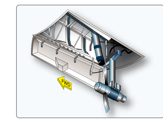
A Ram Air Turbine (RAT) is the last line of defense in the multi-layered power-redundancy architecture of transport-category aircraft. Consisting of a small, propeller-driven turbine or axial fan that deploys directly into the free airstream, the RAT converts the kinetic energy of relative wind into hydraulic pressure, electrical power, or both — delivering just enough energy to maintain controlled flight and execute an emergency approach when every other power source has been lost. For ATP candidates, understanding the RAT in depth means grasping not only what it does but how it fits within the broader requirements of 14 CFR Part 25, why its output characteristics force specific crew procedures, and how various aircraft architectures implement it differently.
The Power-Redundancy Architecture That Defines the RAT's Role
Transport aircraft certified under 14 CFR Part 25 must demonstrate that no single failure — and in many cases no combination of two independent failures — will result in loss of the aircraft. Electrical and hydraulic power is therefore supplied through multiple, independent sources: engine-driven generators and hydraulic pumps on each engine, an Auxiliary Power Unit (APU) for ground operations and airborne backup, dedicated battery buses, and, at the very bottom of the hierarchy, the RAT. The APU is a small onboard gas-turbine engine; it burns fuel, runs compressors, and can supply substantial electrical and pneumatic power. The RAT, by contrast, carries no fuel, requires no combustion, and produces power only as long as the aircraft is moving through the air fast enough to spin its blades. These are fundamentally different systems serving different tiers of redundancy, and conflating them is a classic ATP written-test error.
The scenario that calls for RAT deployment — simultaneous loss of all engine-driven generators and APU, or a catastrophic hydraulic system failure — is statistically rare but operationally well-documented. The 1983 Air Canada Boeing 767 fuel exhaustion over Gimli, Manitoba, is frequently cited in training: with both engines flamed out, the flight crew manually deployed the aircraft's air-driven generator (an early RAT-like unit) to provide essential hydraulic and electrical power for flight controls, enabling the crew to glide the aircraft to a safe landing. That aircraft's design required manual extension rather than the automatic dual-channel deployment logic used on many modern transport aircraft. That real-world event underscores exactly what the RAT is designed to accomplish: not full restoration of normal operations, but enough authority to keep the airplane flying and land it safely.
Physical Design and Deployment Mechanics
The RAT unit is typically stowed flush against the fuselage — common locations include the forward belly, the nose section, or the wing root — and is held in place by a mechanical latch. Deployment swings the unit on an arm or door into the slipstream, where aerodynamic forces immediately begin spinning the turbine. On most modern aircraft, deployment is automatic: dual-channel logic continuously monitors bus voltage and hydraulic pressure; when both drop below defined thresholds simultaneously, the deployment latch releases without crew input. A manual deployment switch or handle in the cockpit provides a backup initiation path, and good crew resource management dictates that crews do not wait for automatic deployment if they have confirmed total power loss — they manually deploy the RAT immediately.
Once deployed in flight, the RAT cannot be retracted on the vast majority of transport-category aircraft. The aerodynamic loads on the extended unit are too great for the retraction mechanism to overcome, and the design intentionally prevents inadvertent stowage during an emergency. Re-stowing the RAT after landing requires specific maintenance procedures, including verifying the turbine has fully stopped, resetting the deployment mechanism, and performing a functional check before the next flight. This maintenance action is logged and inspected under the aircraft's approved maintenance program.
Power Output: What the RAT Supplies — and What It Does Not
The RAT is deliberately sized to be a minimum-essential power source, not a full-replacement power source. On a typical widebody aircraft the RAT might drive a single hydraulic circuit supplying the essential flight control surfaces — usually ailerons, elevators, and rudder — while simultaneously powering a single essential AC or DC electrical bus that keeps critical avionics, attitude and navigation instruments, and communications radios alive. Everything else — cabin lighting, entertainment systems, galley power, secondary flight displays, non-essential bus items — is shed automatically when the aircraft transitions to RAT-only power. Crews must be trained to recognize this load-shedding and not be surprised by darkened panels.
On fly-by-wire aircraft such as the Airbus A320 and A330 families, the RAT plays an even more critical role. The flight control computers that interpret sidestick inputs and command control surface actuators require continuous electrical power. Without the RAT, a total power loss would eliminate computer authority entirely, leaving the crew in a degraded mechanical backup mode with severely limited control. Boeing's 787 Dreamliner, with its more-electric architecture and reduced reliance on bleed air, has similarly configured its RAT to sustain the essential flight control and avionics buses when the primary electrical network collapses.
Airspeed Dependency: The Critical Operational Constraint
Because the RAT is an aerodynamic device, its power output is a direct function of airspeed. The relationship is approximately cubic with respect to wind speed across the blades — meaning that relatively modest reductions in airspeed produce disproportionately large drops in available power. Most RATs are certified to produce adequate essential-bus power at speeds at or above a published minimum airspeed, typically in the range of approach speeds for the aircraft type, but crews must understand that as the aircraft decelerates below that range, power output degrades. This drives several critical procedural considerations:
- Expedited descent: Prolonged cruise at high altitude on RAT power wastes time and increases the risk of battery depletion on systems the RAT cannot fully cover. Crews should initiate descent and plan for the nearest suitable airport immediately.
- Airspeed management on approach: Flying a slower-than-normal final approach speed to accommodate a gusty wind correction may push RAT output below acceptable thresholds. Crews must balance obstacle clearance with the need to sustain adequate RAT power.
- Flap and slat limitations: High-lift device operation draws hydraulic power. On many aircraft types, full flap deployment is prohibited or limited under RAT-only hydraulics. This means approach and landing speeds may be significantly higher than normal, demanding longer runway planning.
- Single-engine restart priority: Restoring even one engine-driven generator eliminates dependence on the RAT entirely. Crews should follow the applicable QRH or emergency checklist for engine restart concurrently with RAT-driven flight to restore full system capability as soon as possible.
14 CFR Part 25 Airworthiness Standards and Certification Basis
The requirement for emergency power provisions in transport aircraft flows from 14 CFR Part 25, Subparts F and H, which govern equipment, systems, and installations. While Part 25 does not mandate a RAT by name, it requires that flight-critical systems remain available after specified failure combinations. Manufacturers satisfy these requirements through various means — independent hydraulic systems, battery backups, and RATs — and the chosen solution must be demonstrated by analysis and test during type certification. Once certified, the RAT's deployment logic, output characteristics, and maintenance intervals are defined in the aircraft's Type Certificate Data Sheet and Airplane Flight Manual (AFM), which is itself FAA-approved. Pilots operating under 14 CFR Part 121 receive training on emergency systems, including RAT operation, under the initial, transition, and recurrent training requirements of 14 CFR Part 121 Subpart N (e.g., §§121.400, 121.415, 121.424), and the AFM limitations section governs what operations are permissible on RAT power.
Key Numbers, Rules, and Limitations
- RAT deployment is typically automatic on loss of all primary generators and hydraulic pressure below threshold values defined in the AFM.
- Manual deployment should not be delayed — crews initiate it immediately upon confirming total power loss per emergency checklists.
- RAT supplies only essential systems: one hydraulic circuit and one or two electrical buses; non-essential loads are automatically shed.
- Power output is speed-dependent and decreases with lower airspeeds — a cubic relationship means even a moderate speed reduction cuts power significantly.
- The RAT cannot be retracted in flight on most transport-category aircraft; re-stowing requires maintenance action on the ground.
- Flap extension may be limited or prohibited under RAT-only hydraulic power, raising landing speeds and runway length requirements.
- Battery backup systems complement the RAT; crews must monitor battery state to ensure continued essential bus power throughout the approach and landing.
Common Test Traps
- RAT versus APU: The APU is a fuel-burning gas turbine providing substantial backup power; the RAT is a purely aerodynamic device of last resort. Test distractors often present them as equivalent or interchangeable.
- Full power restoration myth: The RAT does not restore full aircraft electrical and hydraulic power. It powers only essential, minimum-flight systems. Any answer choice implying normal operations resume on RAT power is incorrect.
- Constant-output assumption: The RAT does not produce steady, speed-independent power. Its output rises and falls with airspeed; slower flight means less power and potentially inadequate essential-system coverage.
- In-flight retraction: On virtually all transport-category aircraft the RAT cannot be retracted while airborne. Selecting RAT deployment is operationally irreversible until landing and maintenance re-stow.
- Forgetting flap limitations: Questions may test whether candidates know that approach configuration is constrained under RAT-only hydraulics, requiring awareness of increased landing speeds and runway requirements.