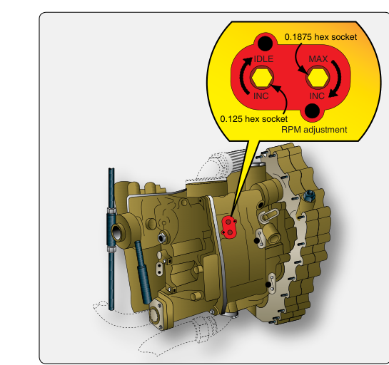
The Fuel Control Unit — often abbreviated FCU, and sometimes called a fuel control or hydromechanical fuel control — is one of the most sophisticated components an Aviation Maintenance Technician (AMT) will encounter on a turbine powerplant. It serves as the primary interface between the pilot's power demand and the engine's physical fuel delivery system, continuously computing and metering the exact quantity of fuel the engine needs at any given moment. Understanding how the FCU operates, what it controls, and how adjustments are made is essential knowledge for the AMT Powerplant certificate and, more importantly, for safe, airworthy maintenance practice.
Unlike a piston engine carburetor that reacts mainly to throttle position and venturi pressure, a turbine FCU must simultaneously monitor and respond to multiple variables: compressor inlet temperature, compressor discharge pressure, engine speed (N1 and/or N2), throttle lever angle, and in many designs, aircraft altitude and Mach number. This multi-variable computation is what allows the engine to produce stable, predictable thrust across a huge envelope — from sea-level takeoff on a hot day to cruise at 40,000 feet.
How the FCU Works
Most FCUs encountered on transport and business turbine aircraft are hydromechanical in basic design, meaning their core computing elements are mechanical levers, bellows, cams, and hydraulic servo valves rather than digital electronics. Many modern engines overlay an Electronic Engine Control (EEC) or Full Authority Digital Engine Control (FADEC) on top of a hydromechanical base, but the fundamental metering hardware remains similar. In a FADEC-equipped engine the electronic unit has full authority over fuel scheduling, while on older or simpler engines the hydromechanical FCU alone governs fuel flow.
Metering Valve and Pressure Drop
At the heart of every FCU is a metering valve. High-pressure fuel from the engine-driven fuel pump flows into the FCU, and the metering valve positions itself to create a calibrated orifice. Because flow through an orifice depends on both orifice size and the pressure differential across it, the FCU includes a differential pressure regulator (also called a pressure-drop regulator or bypass valve) that maintains a constant pressure drop across the metering valve — the exact value is engine-specific and set by the manufacturer's design data. With a constant pressure drop maintained, fuel flow becomes a direct function of metering valve opening area alone, allowing precise, repeatable scheduling.
Computing Section
The computing section translates engine operating parameters into a metering valve command. Key sensing inputs include:
- Compressor Inlet Temperature (T2 or CIT): A bellows or bi-metallic sensor detects inlet air temperature. Colder, denser air allows more fuel; warmer air requires less to avoid overtemperature.
- Compressor Discharge Pressure (P3 or CDP): An aneroid bellows or servo measures P3 and schedules fuel flow to maintain the desired fuel-to-air ratio. As the throttle is advanced and the compressor speeds up, P3 rises and allows more fuel.
- Engine Speed (N1/N2): A flyweight governor or an electrically driven speed signal compares actual rotor speed to demanded speed. If actual speed exceeds the demanded value, the governor reduces fuel flow; if below, it increases flow.
- Power Lever Angle (PLA): The pilot's throttle physically repositions cams and levers in the FCU that set the target operating point — essentially the reference around which all other parameters compute corrections.
Acceleration and Deceleration Schedules
One of the FCU's most critical functions is preventing compressor stall during acceleration and rich blowout or flameout during deceleration. If the pilot slams the throttle forward, a simple system would flood the combustor with far more fuel than the compressor can support, causing a stall or an overtemperature. The FCU's acceleration schedule — a cam or electronic schedule — limits how quickly fuel flow can increase relative to compressor pressure rise. Similarly, a deceleration schedule prevents fuel flow from dropping so fast that the flame extinguishes. These schedules are among the most important and carefully calibrated elements of the FCU.
Limiting Functions
Modern FCUs also enforce hard limits that protect the engine regardless of throttle demand:
- Maximum fuel flow (Wf max): Prevents overtemperature in the turbine section by capping fuel regardless of throttle position.
- Minimum fuel flow (Wf min): Ensures a lean-extinction limit is not crossed during rapid deceleration or descent.
- Overspeed governing: If rotor speed exceeds a manufacturer-defined trip point above 100% rated speed, the FCU sheds fuel to prevent destructive centrifugal loads. The exact trip percentage is engine-specific and defined in the manufacturer's data, since brief excursions near 100% can occur during normal operation.
- Temperature limiting (T4/EGT limiting): In many designs, a dedicated turbine temperature limiter circuit or trimmer within the FCU or EEC reduces fuel flow if exhaust gas temperature approaches its redline.
Why It Matters
The FCU is safety-critical in the most direct sense: a miscalibrated or malfunctioning FCU can cause an uncontained engine failure from overspeed, a catastrophic hot section burnout from overtemperature, or a loss of thrust at a critical flight phase from flameout. Because of this, the FAA requires that all maintenance affecting fuel control adjustments be performed strictly in accordance with the manufacturer's approved maintenance manual, and that the results be verified on an approved test cell or ground run before return to service. Unauthorized or improvised FCU adjustments are among the most serious maintenance errors possible on a turbine powerplant.
From a reliability standpoint, the FCU is also responsible for starting and relighting the engine. The starting fuel schedule — sometimes controlled by the same unit or by a separate start fuel control — must deliver enough fuel to light the combustor without over-temping the turbine during the rotor acceleration transient. Incorrect starting schedules are a common cause of hot starts, which can permanently damage turbine blades in seconds.
FCU Adjustment Procedures
FCU adjustments are highly engine-specific, but several adjustment categories appear across most turbine powerplants:
- Idle speed (N1/N2 at ground idle): Typically set by adjusting a minimum flow stop or idle speed screw on the governor section. The engine is run at stabilized ground idle and rotor speed is compared to the maintenance manual specification — the target percentage of rated speed varies considerably by engine model, so always verify against the specific engine manual rather than a general figure.
- Maximum speed (N1/N2 at takeoff power): Set by adjusting the maximum speed governor stop. The engine must be operated at the rated power condition (often requiring a calibrated test cell) and actual speed compared to specification.
- Acceleration schedule: Trimmed by adjusting cam followers or servo orifice sizes. Verified by timing throttle transients and checking that no compressor stalls or overtemperature exceedances occur during rapid acceleration.
- Deceleration schedule: Similarly verified by confirming no flameout occurs during rapid power reduction from maximum to flight idle.
- Power trim (thrust or torque setting): On many engines, a final power trim adjustment aligns actual thrust output (measured by an engine pressure ratio, EPR, or by torque gauges on turboprops) with the certified takeoff rating. This is often accomplished using a trim adjustment screw on the FCU or by adjusting EEC trim values.
All adjustments require calibrated test equipment — calibrated tachometers, temperature probes, and pressure gauges — traceable to NIST standards. After adjustment, the aircraft's logbook must be updated with the specific adjustments made, the post-adjustment data recorded, and the relevant AMT's signature and certificate number entered per 14 CFR Part 43 requirements.
Key Numbers and Rules
- FCU maintenance must follow the manufacturer's approved maintenance manual and 14 CFR Part 43 — no deviations without an approved data source.
- The constant pressure drop maintained across the metering valve is an engine-specific design value; consult the specific engine manual rather than assuming a general figure.
- Ground idle speed targets vary considerably by engine model and are always specified in the engine manufacturer's maintenance manual — there is no single general percentage that applies across turbofan types.
- A hot start occurs when EGT exceeds the starting temperature limit during engine start — often caused by excess fuel or delayed ignition, not always an FCU fault but frequently related to the starting schedule.
- FADEC-equipped engines typically do not allow manual FCU adjustment of fuel schedules; adjustments are made via approved software and an airborne data loader or ground support equipment.
- After FCU replacement or adjustment, the manufacturer's maintenance manual typically calls for a ground run or functional check before return to service; the specific requirement and its scope are defined by that manual rather than a single blanket FAA rule for every engine type.
Common Test Traps
- Confusing the metering valve with the shutoff valve: The shutoff (or firewall shutoff) valve stops all fuel in an emergency; the metering valve continuously modulates flow during normal operation. They are separate components with separate functions.
- Assuming adjustment is always mechanical: On FADEC engines, the AMT cannot turn an adjustment screw to change fuel scheduling — changes are made electronically with approved ground support equipment, and unauthorized attempts to mechanically override a FADEC FCU can result in an unflyable engine or voided type certificate data.
- Overlooking the differential pressure regulator: Students often focus only on the metering valve and miss that flow accuracy depends equally on maintaining a constant pressure differential. A failed differential pressure regulator causes erratic fuel flow even if the metering valve is perfect.
- Mixing up acceleration vs. deceleration faults: A compressor stall on throttle advance points to a too-rich acceleration schedule or a faulty CDP sensing bellows; a flameout on rapid deceleration points to a too-lean deceleration schedule. These are opposite problems requiring opposite corrective actions.
- Skipping logbook entries after adjustment: Under 14 CFR 43.9 (records of maintenance, preventive maintenance, rebuilding, and alteration) and 43.11 (records of inspections), any maintenance performed — including FCU adjustments — requires a proper maintenance record entry. Omitting this record is not just a paperwork error — it is a federal regulatory violation.