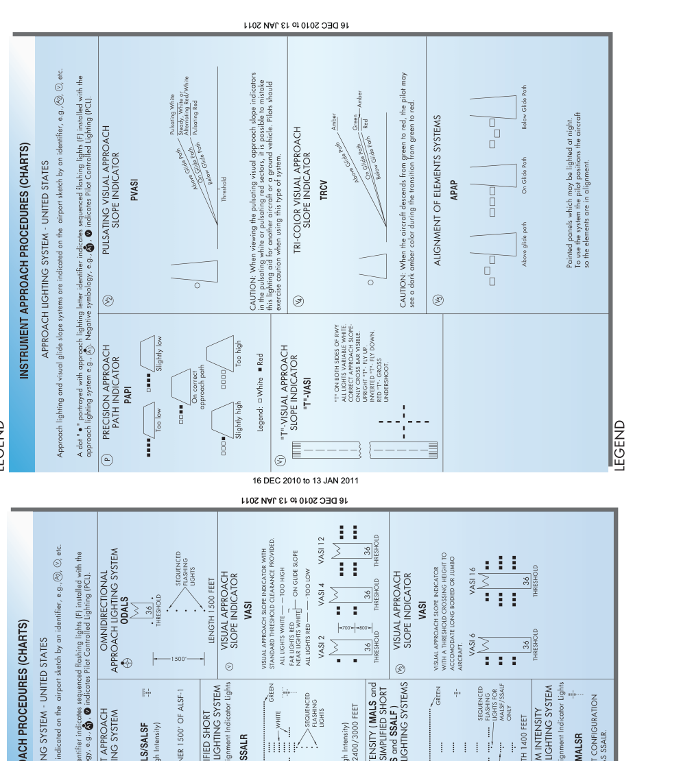
When an instrument approach brings you down through the clouds, the approach lighting system (ALS) is often the first thing you see before the runway itself comes into view. These arrays of lights, bars, and flashers are precisely engineered to give your eyes an immediate, unambiguous reference during the critical transition from instrument to visual flight. For the instrument-rated pilot, knowing the different ALS configurations, what each one provides operationally, and how they are depicted on approach charts is not merely academic — it directly determines what visibility minimums you can legally fly to and whether you can descend below the decision altitude (DA) or minimum descent altitude (MDA).
This article covers the full landscape of approach lighting systems as defined in the FAA's Instrument Flying Handbook (FAA-H-8083-15), the Instrument Procedures Handbook (FAA-H-8083-16), the AIM, and 14 CFR Part 91, giving you the depth you need to read any approach chart confidently and make legally correct, safety-sound decisions on every approach.
What Approach Lighting Systems Do
An ALS serves one fundamental purpose: to bridge the gap between the instrument environment and the visual environment. As you descend on final approach, your eyes need an immediate, structured reference that tells you three things — where the runway is, what your alignment is, and roughly what your pitch attitude should be. The ALS, extending outward from the runway threshold (typically 1,400 to 3,000 feet depending on system type), gives you all three before the runway markings or threshold lights themselves become visible.
The ALS also provides sequenced flashing lights (SFL) — the famous "rabbit" — which appears to race toward the runway at high speed, drawing the pilot's eyes straight down the approach corridor. This is a powerful attention-getter in low visibility. The ALS does not, however, provide vertical guidance; that remains the function of the ILS glide slope, VASI, PAPI, or similar systems.
The Major ALS Configurations
The FAA and ICAO have standardized several ALS configurations. The most important ones for IFR operations in the United States are:
- ALSF-1 (Approach Light System with Sequenced Flashing Lights, Configuration 1): A 3,000-foot system with sequenced flashers and a steady-burning centerline. Used for CAT I ILS approaches. The two rows of crossbars at 500-foot and 1,000-foot marks help judge distance and alignment.
- ALSF-2 (Approach Light System with Sequenced Flashing Lights, Configuration 2): Also 3,000 feet long, the ALSF-2 adds red side-row barrettes in the final 1,000 feet (the touchdown zone area) and is specifically designed to support CAT II and CAT III ILS operations. The red bars create an unmistakable visual contrast against the white centerline lights, aiding roll-out alignment at very low decision heights.
- MALSR (Medium Intensity Approach Light System with Runway Alignment Indicator Lights): A 1,400-foot system with RAIL (sequenced flashers) extending the effective visual reach. This is the most common system at general aviation airports with instrument approaches. It supports lower minimums than a simple MIRL runway but does not reach CAT II capability.
- MALS (Medium Intensity Approach Light System): Similar to MALSR but without the sequenced flashers. Shorter usable range in reduced visibility compared to MALSR.
- ODALS (Omnidirectional Approach Lighting System): Seven sequenced flashing lights, not in a row pattern — five on the approach course and two flanking the threshold. Used at smaller airports with non-precision or circling approaches. Provides minimal alignment information but does give the pilot something to look for in IMC transitions.
- SSALF, SSALR, SSAL (Simplified Short Approach Light System variants): 1,400-foot systems similar to MALS/MALSR but in simplified configurations; often found where terrain or obstacles prevent a full-length ALS. The "R" suffix indicates RAIL (sequenced flashers).
- REIL (Runway End Identifier Lights): Two synchronized flashing lights flanking the threshold, not an ALS per se, but a threshold-identification aid. Important because their presence on a chart symbol affects visibility credit differently from a full ALS.
How ALS Type Affects Your Legal Minimums
This is where ALS knowledge directly enters the cockpit decision. Under 14 CFR §91.175, you may not descend below DA or MDA unless you have the runway environment in sight AND you are in a position to make a normal landing. The FAA defines specific visibility credit for the type of ALS present. Specifically, if the runway has an operative ALS, you may be authorized to fly lower visibility minimums than if the runway had only approach lights or no lights at all.
On standard instrument approach procedure (SIAP) charts, the minimums section lists different visibility values corresponding to aircraft approach categories AND the type of visual aids present. The notes at the bottom of the chart typically state something like "visibility reduced by RVR 4000 when operative MALSR in use" or show bracketed lower visibility figures. The hierarchy, from highest to lowest visibility credit (and thus lowest published minimums), generally follows: ALSF-2 > ALSF-1 > MALSR/SSALR > MALS/SSAL > REIL or ODALS > no approach lights.
Practically, this means that if the MALSR is out of service (NOTAM'd), you must use the higher visibility minimum listed for the "no ALS" column on the chart, even if everything else about the approach is normal. Checking NOTAMs for ALS status is therefore a non-optional preflight task.
Reading ALS Symbols on Approach Charts
On Jeppesen and FAA/NACO approach charts, the airport diagram in the lower-right corner depicts the runway environment with standardized symbols. ALS configurations appear as a row of dots or squares extending outward from the threshold on the appropriate runway end. The specific symbol pattern varies slightly by chart publisher but the AIM and the chart legend identify each:
- A long row of filled squares or circles on the approach end = full ALS (ALSF-1 or ALSF-2)
- A shorter row = MALS, SSAL, or abbreviated system
- A zigzag or lightning-bolt symbol within the row = RAIL or sequenced flashers present
- Two small squares flanking the threshold with no centerline row = REIL only
- The specific system type (e.g., "MALSR") is usually printed alongside or in the airport notes section of the chart
On FAA terminal procedure publications (government charts), you will also see ALS information encoded in the minimums section itself, where parenthetical or bracketed RVR/visibility values correspond to a footnote identifying which ALS category is operative. Always cross-reference the airport diagram, the minimums table, and the chart notes together.
Why This Matters in Real IMC Operations
Understanding ALS configurations is not just a knowledge test item — it has direct safety implications. The ALS is the primary visual transition cue as you break out of the clouds. A pilot who does not recognize that a runway has only an ODALS (with no centerline guidance) may be surprised to find minimal directional information upon breakout, especially in cross-wind conditions. Conversely, a pilot who sees the ALSF-2's red side-row barrettes for the first time without prior study may momentarily misinterpret the visual picture.
Additionally, if you break out of clouds at MDA and see only approach lights (no runway environment), 14 CFR §91.175(c)(3)(i) permits you to descend from MDA to 100 feet above TDZE if the approach lights are in sight — but only if the system has red terminating bars or red side-row barrettes. The ALSF-2 qualifies; a simple MALS does not. This is a nuanced rule that directly rewards knowing which system is installed.
Key Numbers and Rules
- ALSF-1 / ALSF-2: 3,000 feet long; supports CAT I (ALSF-1) and CAT II/III (ALSF-2)
- MALSR / MALS / SSALR / SSAL: 1,400 feet long; supports non-precision and CAT I approaches
- ODALS: Seven lights; most basic ALS; primarily non-precision or circling
- 100-foot rule (§91.175): With red terminating bars or red side-row barrettes in sight, you may descend to 100 feet above TDZE from MDA
- NOTAM impact: An inoperative ALS requires use of the higher (more restrictive) published visibility minimum
- RVR vs. visibility: ALS credit is often expressed in RVR (e.g., RVR 4000 vs. RVR 5000); know the RVR-to-statute-mile conversion table in the AIM
Memory Aid
For the ALS hierarchy, remember the phrase "Full, Medium, Simple, Omni" — moving from the most capable (ALSF full 3,000-foot system) down to medium-length systems (MALSR/MALS), to simplified short systems (SSALR/SSAL), to the basic omnidirectional ODALS. Each step down in the hierarchy generally means higher published visibility minimums and less positional guidance at breakout.
Common Test Traps
- Confusing REIL with ALS: REIL provides threshold identification only, not approach course alignment. Charts may show REIL symbols that look superficially similar to abbreviated ALS symbols; read the legend carefully.
- Ignoring the ALS NOTAM: A test scenario may state the ALS is out of service and ask which visibility minimum applies. Always default to the no-ALS column when the system is inoperative.
- The 100-foot descent rule: Many students memorize that approach lights alone let you descend below MDA, but forget the rule requires red terminating bars or red side-row barrettes — features of the ALSF-2 and not found on MALS/MALSR.
- System length confusion: The FAA knowledge test sometimes exploits confusion between 1,400-foot and 3,000-foot systems. A 3,000-foot ALS is a high-intensity full system; 1,400 feet is the medium/simplified category.
- Chart symbol vs. system name: The airport diagram symbol tells you where the lights are and approximately what type; the actual system designation is found in chart notes, NOTAMs, or the A/FD (Chart Supplement). Do not assume a symbol equals a specific system without confirming the designation.