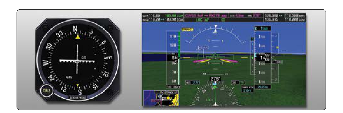
The Instrument Landing System (ILS) is the gold standard of precision instrument approaches available to general aviation pilots in the United States. Unlike non-precision approaches, the ILS provides both lateral and vertical guidance all the way to the runway threshold, allowing pilots to descend through clouds and low visibility with a high degree of confidence — provided the aircraft, crew, and airport all meet specific requirements. Understanding ILS minimums is not just a knowledge-test topic; it is a fundamental safety skill that every instrument-rated pilot must internalize before venturing into instrument meteorological conditions (IMC).
When you look at an ILS approach plate, you will notice a set of minimums expressed as a Decision Altitude (DA) — sometimes still called Decision Height (DH) on older plates — paired with a required visibility. These numbers are not arbitrary. They are the lowest point to which you may descend and the least visibility you must have before you can legally continue to a landing. Miss either threshold, and a missed approach is mandatory. This article explains how those numbers are set, what they mean operationally, and the critical details the FAA knowledge test loves to probe.
How the ILS Works
An ILS consists of three separate radio components working together. The localizer transmits a course signal aligned with the runway centerline on a frequency between 108.10 and 111.95 MHz (odd tenths only). It provides left-right guidance within roughly 10 degrees of the runway heading. The glide slope transmits a vertically angled signal — typically 3 degrees above horizontal — giving the pilot precise up-down guidance from the final approach fix (FAF) to the runway. Finally, marker beacons (outer, middle, and inner) or distance measuring equipment (DME) provide range information along the approach path, telling the pilot how far from the threshold they are.
The glide slope intersects the localizer course at a specific angle calculated to bring the aircraft to the runway touchdown zone at the correct descent rate. At a typical 3-degree glide slope, a pilot flying at 90 knots groundspeed will descend at approximately 480 feet per minute. The glide slope antenna is positioned about 1,000 feet down the runway from the threshold and offset to one side; its signal is calibrated so that following it correctly places the aircraft in the touchdown zone.
The precision of the ILS — specifically its ability to provide vertical guidance — is what earns it the classification of a precision approach under 14 CFR Part 97 and the Aeronautical Information Manual (AIM). This distinction directly drives the lower minimums that ILS approaches enjoy compared to VOR or GPS non-precision approaches.
Decision Altitude and Decision Height Explained
Decision Altitude (DA) is expressed in mean sea level (MSL) altitude and is the published minimum descent point on a precision approach. When the altimeter reads DA, the pilot must have the required visual references in sight to continue the approach. Decision Height (DH), by contrast, is expressed as a height above the touchdown zone elevation (TDZE), which is printed on the approach plate. Modern FAA approach charts favor the term DA and express it as an MSL value, but you may see DH on older ILS plates or when referencing Category II/III operations. For practical purposes at the student level, they represent the same decision point: the floor below which you cannot descend without the required visual cues.
It is critical to understand that DA is not a minimum descent altitude you level off at while searching for the runway. The aircraft is still descending through DA. The rule, per the AIM, is that if the required visual references are not clearly visible and identifiable at DA, the pilot immediately initiates the missed approach. Continuing below DA without visual references is a serious violation of 14 CFR 91.175 and an acute safety hazard.
Categories of ILS Operations
ILS approaches are divided into performance categories that determine how low the minimums can go. These categories depend on the aircraft's approach speed, the installed avionics and autopilot capability, the airport's ground equipment, and the pilot's certification.
- Category I (CAT I): The standard ILS available to instrument-rated private pilots. Minimums are typically a DA of 200 feet above the touchdown zone and a runway visual range (RVR) of 1,800 feet (or in some cases 2,400 feet depending on lighting). This is the approach category printed on the vast majority of ILS plates used in general aviation.
- Category II (CAT II): Requires special aircraft certification, a trained crew, a CAT II-certified airport, and specific FAA authorization. Minimums can go as low as a DH of 100 feet and an RVR of 1,200 feet.
- Category III (CAT III): Divided into subcategories (IIIa, IIIb, IIIc), these approaches involve autopilot or autoland systems and can result in zero-zero minimums for IIIc. These operations are entirely outside the scope of standard instrument rating training and require type-specific authorizations.
For the instrument rating knowledge test and practical exam, students are primarily expected to understand and apply Category I minimums. Categories II and III appear on the test in a conceptual sense — you should know they exist and require special authorization — but you will not be expected to fly them.
Reading ILS Minimums on the Approach Chart
ILS minimums are found in the minimums section at the bottom of a Jeppesen or NACO (FAA) approach plate. On NACO plates, the minimums are organized in rows by approach category (S-ILS for straight-in ILS, with aircraft speed category columns A, B, C, D) and in columns for visibility or RVR. The published DA(H) value, for example, might read 200 (1–½), meaning 200 feet AGL / 1.5 statute miles visibility, or it may specify an RVR value such as RVR 1800.
The visibility minimum may be listed as either statute miles or RVR in feet. When the approach plate specifies RVR, that value applies if RVR equipment is operational at the airport. If RVR is unavailable, pilots must convert to statute miles using published conversion tables in the AIM. An RVR of 1,800 feet generally corresponds to a visibility of approximately ¼ statute mile.
Approach plates also list the touchdown zone elevation (TDZE) and the threshold crossing height (TCH), which is the approximate height of the glide slope above the threshold. A typical TCH of 50 to 55 feet confirms the glide slope geometry is correct for a standard aircraft. Pilots should verify the TCH is appropriate for the aircraft wingspan and antenna location.
Legal Requirements to Begin and Continue an ILS Approach
Under 14 CFR 91.175, a pilot operating under IFR may not begin a final approach segment unless the latest weather report for the airport indicates conditions at or above the published minimums. However, a pilot may continue an approach past the final approach fix even if weather goes below minimums after the approach has commenced — the decision is made at DA. If at DA the required visual references are not in sight, a missed approach must be executed immediately.
The required visual references that allow a pilot to continue below DA include at least one of the following: the approach light system (ALS), the threshold, threshold markings, threshold lights, the runway end identifier lights (REIL), the visual approach slope indicator (VASI), touchdown zone or touchdown zone markings, or runway or runway markings. Simply seeing a glow through the clouds does not count. The reference must be clearly identifiable.
Key Numbers and Rules
- CAT I ILS DA(H): Typically 200 feet HAT (height above touchdown zone) and RVR 1,800 feet (or ½ sm visibility).
- Glide slope angle: Normally 3 degrees; produces approximately 300 feet per nautical mile descent rate.
- Localizer frequency range: 108.10–111.95 MHz, odd tenths only.
- Glide slope frequency: Automatically paired when localizer is tuned; no separate tuning required.
- Outer marker (OM): Located 4–7 miles from runway; blue light, continuous dashes in audio (— — —).
- Middle marker (MM): Located about 3,500 feet from threshold near DA intercept; amber light, alternating dot-dash in audio (· — · —).
- FAR 91.175 requirement: Flight visibility must meet or exceed published minimums to descend below DA/MDA; must have required visual references.
- ILS critical area: Ground vehicles and aircraft must not enter the ILS critical area when weather is below 800 feet ceiling or 2 miles visibility, to avoid interference with the signal.
Common Test Traps
- DA vs. MDA confusion: The ILS uses a Decision Altitude, not a Minimum Descent Altitude. MDA applies to non-precision approaches. At MDA, you may level off; at DA, you are still descending and must decide immediately.
- RVR vs. statute miles: The test may give you an RVR value and ask whether conditions meet minimums expressed in statute miles, or vice versa. Know the conversion table from the AIM and never assume 1 RVR = 1 sm.
- Beginning vs. continuing an approach: 14 CFR 91.175 allows you to continue below the FAF even if conditions drop below minimums after you've begun — but you must execute the missed approach at DA if visual references are absent. The test exploits this nuance.
- Required visual references: Seeing just the approach light system alone (without seeing additional threshold or runway environment references) only permits descent to 100 feet above TDZE — not all the way to the runway. This is an often-tested detail from 14 CFR 91.175(c)(3).
- Glide slope inoperative: If the glide slope fails, the ILS degrades to a localizer-only (LOC) approach. LOC minimums are higher (worse) than ILS minimums and are listed separately on the chart. Never attempt to descend to ILS minimums on a LOC-only approach.
Putting It Together: The Practical Picture
On a typical CAT I ILS approach in a light general aviation aircraft, you will intercept the localizer outside the final approach fix, establish yourself on the glide slope, and descend at roughly 500 feet per minute while cross-checking your position with DME or marker beacons. As you pass the middle marker, you are approximately 3,500 feet from the threshold and should be near DA. At DA, you have roughly three seconds to make your go/no-go decision. If the runway environment is visible and identifiable, continue visually. If not, execute the missed approach without hesitation. That three-second window is why instrument pilots train repeatedly for the go-around — hesitation below DA in IMC has been a factor in numerous fatal accidents.
Thorough knowledge of ILS minimums — what they mean, how they are published, and what the regulations require — is the foundation of safe instrument flying. Mastering this topic protects you in the air and ensures you are well-prepared for both the FAA knowledge test and the instrument rating practical exam.