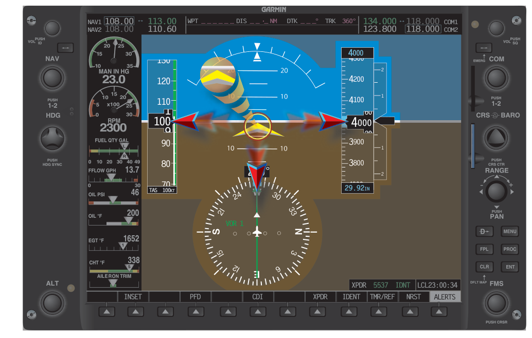
Flying in the clouds demands unwavering trust in your instruments — but that trust must be earned, not assumed. Instrument errors, whether caused by pitot-static blockages, vacuum pump failures, or subtle gyroscopic precession, have contributed to numerous fatal accidents where pilots continued to rely on instruments that were feeding them false information. The ability to detect erroneous instrument indications quickly and cross-check remaining reliable instruments is therefore one of the most critical skills an instrument-rated pilot can develop.
This article walks through the mechanics of how common instrument failures manifest, how to build a systematic scan that catches discrepancies early, and what the FAA expects you to know for both the instrument knowledge test and real-world IFR operations.
The Instrument Scan as the Foundation of Error Detection
The FAA's Instrument Flying Handbook (FAA-H-8083-15) describes the instrument cross-check as the first fundamental skill of attitude instrument flying. A proper cross-check is a continuous, logical sweep of the instruments that extracts only the information needed at that moment. Three main scanning patterns are taught: the selective radial scan, the instrument-to-instrument scan, and the hub-and-spoke scan centered on the attitude indicator. Regardless of which technique you use, the goal is identical — no single instrument dominates your attention, and every instrument gets visited often enough that a false reading becomes apparent quickly through comparison with its neighbors.
The attitude indicator (AI) is typically the primary reference for pitch and bank, but it cannot verify itself. That is precisely why the cross-check exists: the supporting instruments confirm or deny what the AI is telling you. If the AI shows wings-level but the turn coordinator shows a steady bank rate, one of them is lying. Knowing which one — and how to figure that out in seconds — is the art and science of instrument error detection.
How Specific Instruments Fail and What You Will See
Pitot-Static System Failures
The pitot-static system feeds three critical instruments: the airspeed indicator (ASI), the altimeter, and the vertical speed indicator (VSI). A blocked or partially blocked pitot tube or static port produces characteristic and often deceptive errors.
- Blocked pitot tube (with static port open): The trapped pitot pressure stays constant while the static pressure continues to change with altitude, so the ASI effectively behaves like an altimeter. As you climb, the ASI reads higher than actual. As you descend, the ASI reads lower than actual. On approach, the ASI may show a misleadingly high or increasing airspeed trend even as you slow — a dangerous deception.
- Blocked static port (pitot open): The altimeter freezes at the altitude where the blockage occurred. The VSI freezes at zero. The ASI becomes unreliable — it will read higher than actual during a climb and lower than actual during a descent, because the trapped static pressure cannot change. Activating the alternate static source (which draws from lower-pressure cabin air) restores these instruments, though the altimeter will read slightly higher and the ASI slightly faster than normal; this error is listed on a placard in the aircraft or in the POH.
- Pitot heat failure with icing conditions: Ice can close the pitot tube gradually; the ASI may drop toward zero while all other instruments remain normal. This scenario famously mimics an airspeed loss during climb — treat it as an unreliable airspeed situation.
Vacuum System and Gyroscopic Instrument Failures
Attitude indicators and heading indicators driven by a vacuum-powered gyro depend on continuous suction — typically 4.5 to 5.4 inches of mercury for most general aviation systems. A failing vacuum pump often produces a gradual power reduction rather than an abrupt cutoff. This means the gyros slowly tumble or precess with no dramatic flag to announce the failure. The insidious characteristic of vacuum failure is that the instruments may appear plausible for minutes after the pump has failed.
- Attitude indicator failure signs: The miniature aircraft slowly rolls or pitches without corresponding control input. During coordinated flight, a functional AI should remain steady. Increasing divergence between the AI and the turn coordinator is a strong warning flag.
- Heading indicator failure signs: The HI drifts rapidly (more than the expected 3° per 15 minutes), or it fails to respond when you initiate a turn confirmed by the turn coordinator and magnetic compass. Cross-checking the HI against the magnetic compass and the GPS track (when available) reveals the discrepancy.
- Vacuum gauge — your first-line detector: Checking the suction gauge regularly during flight is a critical habit. A reading below 4.5 or above 5.4 inches of mercury warrants immediate skepticism toward gyroscopic instruments.
Electrical and Gyroscopic Failures in Electric Systems
Many aircraft use an electrically driven attitude indicator as a backup, or rely entirely on electric gyros. An alternator failure or bus fault may cause electric instruments to fail together, making the cross-check against pitot-static instruments even more important. The turn coordinator, which is almost always electrically driven, serves as the primary bank reference when the vacuum-driven AI becomes unreliable. Knowing which instruments on your aircraft are vacuum-driven and which are electric is essential preflight knowledge — this separation is what allows partial-panel flight.
The Systematic Cross-Check for Error Detection
The FAA recommends a structured method for identifying a suspect instrument: compare, verify, and maintain control. When two instruments disagree, do not immediately assume one is wrong — instead, bring a third instrument into the comparison. This triangulation approach is at the heart of instrument error detection.
For example, if the attitude indicator shows a 10° right bank but the turn coordinator shows wings-level and the altimeter and VSI are both steady, the weight of evidence points to an AI failure. Conversely, if the turn coordinator shows a left turn and the altimeter is unwinding while the AI shows wings-level, the AI may have tumbled. Commit to flying by the reliable instruments and, if workload permits, flag the failed instrument by covering it or mentally excluding it from your scan.
During approach, a common cross-check is comparing the ASI to the aircraft's power setting and pitch attitude. If you are at approach power and a normal nose-low pitch attitude but the ASI reads unusually high or is climbing rather than stabilizing, suspect a pitot-static anomaly before blindly reducing power further.
Why This Matters — The Safety Record
The NTSB and FAA accident data consistently show that loss-of-control accidents in IMC are frequently preceded by instrument failures that went undetected or were misdiagnosed. Spatial disorientation, which can develop within seconds of an undetected AI failure, is a leading cause of fatal general aviation accidents. The cross-check is not a procedural nicety — it is the mechanism by which pilots prevent subtle false readings from becoming fatal illusions.
Additionally, 14 CFR Part 91.205 requires specific instruments to be operational for IFR flight. If a required instrument fails in flight, the regulations govern whether you can continue under IFR and what equipment must remain serviceable. Understanding the minimum equipment list (MEL) concept and the regulatory requirements reinforces why each instrument in the IFR panel is there and what happens when it is absent.
Key Numbers and Rules
- Normal vacuum suction range: approximately 4.5–5.4 in. Hg for most GA aircraft (always verify in the specific POH).
- Heading indicator drift tolerance: up to approximately 3° per 15 minutes is considered normal; excessive drift suggests precession or failure.
- Alternate static source effect: altimeter reads slightly high, ASI reads slightly fast; exact values on placards or POH.
- Required IFR instruments (14 CFR 91.205(d)): gyroscopic rate-of-turn indicator, slip/skid indicator, sensitive altimeter, clock with hours/minutes/seconds, attitude indicator, heading indicator, and the applicable VOR/ILS equipment — all must be operational for IFR departure.
- Turn coordinator flag: an off flag on the turn coordinator indicates electrical failure of that instrument; do not use it as a bank reference.
- Partial panel standard: use the turn coordinator, altimeter, VSI, and ASI as primary references when gyroscopic AI and HI are inoperative; the magnetic compass provides heading after allowing for turning and acceleration errors.
Common Test Traps
- Blocked pitot vs. blocked static confusion: Test questions often swap these scenarios. Remember — a blocked static port freezes the altimeter and VSI and makes the ASI unreliable in both directions; a blocked pitot tube primarily affects the ASI and makes it behave like an altimeter (reads high on climb, low on descent).
- Alternate static source always adds altitude and airspeed: Students often forget that the lower cabin static pressure causes the altimeter to over-read and the ASI to over-read. The test will ask which direction the errors go.
- Vacuum failure is gradual, not abrupt: Exam scenarios may describe a slow roll or pitch divergence building over several minutes — students sometimes miss this as a failure scenario because there is no sudden flag. Recognize gradual gyro winding-down as a vacuum failure signature.
- Turn coordinator vs. attitude indicator function: The turn coordinator measures rate of roll and rate of turn, not bank angle directly. It cannot replace the AI for pitch information — only for roll trend. Confusing these functions leads to incorrect answers on partial-panel questions.
- Compass errors during partial panel: On a knowledge test, magnetic compass turning errors (undershooting northerly headings, overshooting southerly headings in the Northern Hemisphere) are frequently tested in the context of partial-panel flight. Do not assume the compass reads accurately in a bank.