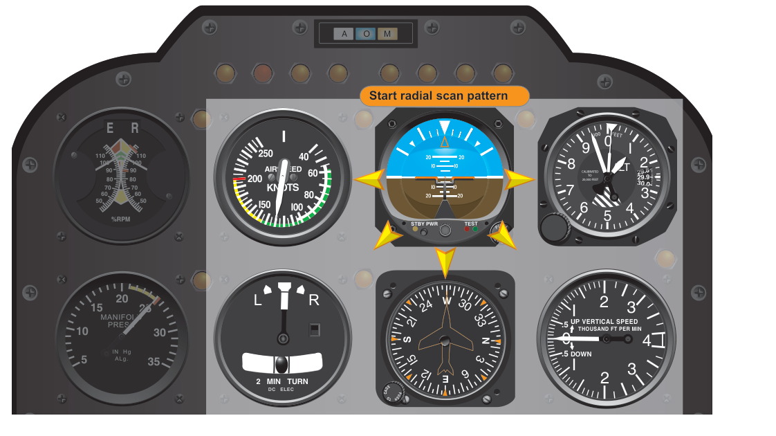
Flying in instrument meteorological conditions (IMC) demands that a pilot extract accurate, continuous information from a panel of gauges and translate that information into precise control inputs—all without any outside visual reference. The skill that makes this possible is the instrument scan: a disciplined, systematic pattern of eye movement across the flight instruments. Without a reliable scan, even a well-trained pilot can fixate on a single instrument, miss a developing deviation, or—worst of all—fall prey to spatial disorientation. The FAA recognizes two primary scan philosophies taught to instrument students: the radial scan (also called the hub-and-spoke or cross-check scan) and the selective scan (also called the selective radial scan or emphasis scan). Understanding both methods, when to use each, and the cognitive traps that disrupt them is foundational knowledge for any instrument rating candidate.
Before examining the techniques themselves, it helps to understand the underlying concept of the attitude instrument flying framework. According to the Instrument Flying Handbook (FAA-H-8083-15), all flight instruments can be classified by function—pitch instruments, bank instruments, and power instruments—and by role: primary (the instrument giving the most pertinent information for a given flight phase) or supporting (instruments that back up or confirm the primary). The scan techniques described below are built around these classifications, with the attitude indicator (AI) typically serving as the central reference from which the pilot radiates outward.
The Attitude Indicator as the Scan's Hub
The attitude indicator is the single most important instrument during instrument flight because it provides a direct, real-time depiction of both pitch and bank simultaneously. Unlike the altimeter or airspeed indicator, which show the results of attitude changes after a lag, the AI shows the aircraft's actual orientation the moment it begins to change. For this reason, the AI serves as the hub of both major scan methods. Every scan pattern begins and returns to the attitude indicator, using its information to set or correct the aircraft's pitch and bank before cross-checking the other instruments for confirmation.
The Radial Scan Method
The radial scan (sometimes called the hub-and-spoke scan) treats the attitude indicator as the center of a wheel. The pilot's eyes move outward from the AI to one of the surrounding instruments—altimeter, airspeed indicator, heading indicator, vertical speed indicator, turn coordinator—read that instrument briefly, then return to the AI before moving out to the next instrument. The pattern looks like the spokes of a wheel radiating from the hub. A typical sequence might be: AI → altimeter → AI → airspeed → AI → heading indicator → AI → vertical speed indicator → AI, cycling through all relevant gauges.
The key discipline in the radial scan is the return to the hub. After reading any peripheral instrument, the pilot's gaze must come back to the AI. This prevents the most dangerous scanning error—fixation—where a pilot stares at one instrument (often the altimeter during a busy approach) while the aircraft's bank or pitch is changing undetected. By always returning to the AI, the pilot keeps attitude control as the highest priority and uses all other instruments in a supporting role.
The radial scan is especially effective during attitude changes and transitions between flight phases. When initiating a climb, for example, the pilot sets the pitch attitude on the AI, then checks airspeed and VSI to confirm the expected performance, then verifies heading on the HI, always returning to the AI between each check. The method works well when all instruments are equally important and the workload of tracking multiple parameters is high.
Rhythm and Dwell Time
A common beginner mistake is spending the same amount of time on every instrument regardless of what it is showing. Experienced pilots develop a sense of dwell time—they linger longer on an instrument that is trending away from the target value and return to the AI more frequently when the aircraft is in an unsteady condition. During stable, straight-and-level cruise in smooth air, the scan can be slower and more deliberate. During a procedure turn or instrument approach in turbulence, the scan must be rapid and AI-centered, with only quick glances at peripheral gauges.
The Selective Scan Method
The selective scan is a refinement of the radial scan designed for specific flight phases where certain instruments become more critical than others. Rather than cycling through all instruments with roughly equal frequency, the pilot selects a primary instrument for each axis of control and devotes the greatest share of scan time to that instrument, while still periodically checking the supporting instruments.
To understand the selective scan, recall the FAA's primary-and-supporting classification. During straight-and-level unaccelerated flight, the primary pitch instrument is the altimeter (it shows whether pitch is producing the correct altitude), the primary bank instrument is the heading indicator (it shows whether bank is holding the correct heading), and the primary power instrument is the airspeed indicator. The attitude indicator supports all of these—it helps the pilot make attitude adjustments—but in terms of telling the pilot what the aircraft is actually doing in terms of performance, those primary instruments carry the most weight for their respective axes.
In the selective scan, the pilot's eyes still radiate from the AI, but the scan is deliberately weighted: more time is spent glancing at the primary instruments for the current flight phase, and the AI is used primarily to set and correct attitude quickly. When a deviation is detected on a primary instrument—say, the altimeter is showing a 100-foot descent—the pilot returns to the AI, makes a small pitch correction, holds it for a moment, then checks the altimeter again to confirm the correction is working. This targeted loop (primary instrument → AI to correct → primary instrument to verify) is the essence of the selective scan.
The selective scan shines during instrument approaches. On a precision approach such as an ILS, the pilot knows that altitude control is critical in the final segment, so the altimeter (and glideslope deviation indicator) receives greater emphasis. On the localizer segment before glideslope intercept, heading and course deviation indicator (CDI) receive more attention. As the approach phase shifts, so does the emphasis of the scan—making it genuinely selective. This dynamic weighting is what separates an advanced instrument pilot from a beginner who scans every instrument with equal priority regardless of what the flight demands.
Why It Matters: Safety and Spatial Disorientation
The instrument scan is not merely an academic exercise—it is the pilot's primary defense against spatial disorientation, a leading cause of fatal accidents in IMC. Without visual reference to the horizon, the vestibular system routinely produces sensations that contradict what the instruments show. A gentle, prolonged bank produces no perceptible sensation of turning, leading to the notorious graveyard spiral. A pilot who trusts the instruments—made possible only by a disciplined scan—can detect and correct such deviations before they become unrecoverable.
A well-executed scan also directly supports precision in instrument flight. Altitude deviations on an IFR flight plan, course deviations on an airway, and airspeed excursions all develop gradually. A scanning pilot catches these deviations when they are small—a 50-foot altitude error is much easier to correct than a 500-foot error discovered after a prolonged fixation on the engine gauges.
Key Numbers and Rules
- Attitude indicator is always the scan hub: Every radial scan spoke begins and ends at the AI.
- Primary-and-supporting classification changes with flight phase: What is primary for level flight differs from what is primary during a climb, descent, or approach.
- Fixation, omission, and emphasis errors are the three scanning errors identified by the FAA: spending too long on one instrument, skipping an instrument entirely, or over-weighting an instrument that is not the primary for the current phase.
- Instrument lag matters: The VSI has inherent lag of several seconds; the altimeter responds more slowly than the AI. Always set attitude on the AI first, then verify on lagging instruments.
- Trim reduces scan workload: A properly trimmed aircraft holds attitude with less pilot input, freeing mental bandwidth for a thorough scan. Instrument pilots trim aggressively.
- Cross-check, interpret, control: The FAA describes the three fundamental skills of attitude instrument flying—continuous cross-check (the scan), instrument interpretation, and aircraft control. These three skills are interdependent; a breakdown in any one degrades the others.
Common Test Traps
- Confusing primary and supporting roles: Many students think the attitude indicator is always the primary instrument. It is the hub of the scan and supports all axes, but during level flight the altimeter is the primary pitch instrument and the HI is the primary bank instrument.
- Misidentifying the primary power instrument: During level, unaccelerated flight, the airspeed indicator is primary for power. During a constant-airspeed climb, the airspeed indicator remains primary for power, while the AI becomes primary for pitch (to maintain attitude that produces the target airspeed).
- Ignoring instrument lag on the VSI: Test questions sometimes describe a pilot chasing the VSI needle during level-off. The correct technique is to set attitude on the AI and wait for the lagging VSI to confirm—not to make continuous small pitch changes in response to VSI fluctuations.
- Treating the scan as static: The selective scan's whole value lies in shifting emphasis as the flight phase changes. Students who memorize one fixed scan sequence may answer questions about approach emphasis incorrectly.
- Forgetting that trim affects scan quality: A question may describe a pilot who is too busy to maintain altitude—often the root cause is an out-of-trim aircraft demanding constant back pressure, which monopolizes attention and degrades the scan.