Modern instrument-rated pilots increasingly fly behind glass cockpits where a single screen — the Primary Flight Display (PFD) — replaces the traditional "six-pack" of individual gauges. At the heart of this architecture is the Air Data Computer (ADC), a dedicated processor that converts raw pitot-static pressures into the precise digital values the PFD uses to draw airspeed tapes, altitude tapes, and vertical speed indicators. For the instrument rating student, understanding how these pieces connect is not optional: it determines how you recognize failures, interpret unusual presentations, and maintain situational awareness when you cannot see outside.
This article walks through what the ADC actually does, how its outputs appear on a typical glass PFD, what can go wrong, and the specific knowledge-test traps the FAA loves to probe on the instrument rating written exam.
What the Air Data Computer Does
The ADC receives three primary inputs from the aircraft's pitot-static system: pitot (ram) pressure, static pressure, and outside air temperature (OAT) from a dedicated probe. From these raw inputs it computes a suite of air-data parameters:
- Indicated airspeed (IAS) — derived from the differential between pitot and static pressure, identical in concept to a traditional airspeed indicator.
- Calibrated airspeed (CAS) — IAS corrected for instrument and position error; the ADC applies these corrections automatically.
- True airspeed (TAS) — CAS corrected for pressure altitude and temperature; useful for flight planning and wind calculations.
- Mach number — relevant in high-performance and turbine aircraft.
- Pressure altitude — derived from static pressure alone using the standard atmosphere model; the altimeter setting (baro correction) is applied digitally.
- Density altitude — computed from pressure altitude and OAT; often displayed as a supplemental readout.
- Vertical speed (VSI) — computed from the rate of change of static pressure over time.
All of these outputs are transmitted digitally — commonly over an ARINC 429 data bus in certified avionics — to the display processor that drives the PFD. Because the computation happens inside a single, sealed unit, there are no aneroid capsules, diaphragms, or mechanical linkages to misalign. The tradeoff is that a single ADC failure can simultaneously remove airspeed, altitude, and VSI from the primary display.
Glass Cockpit PFD Layout and Interpretation
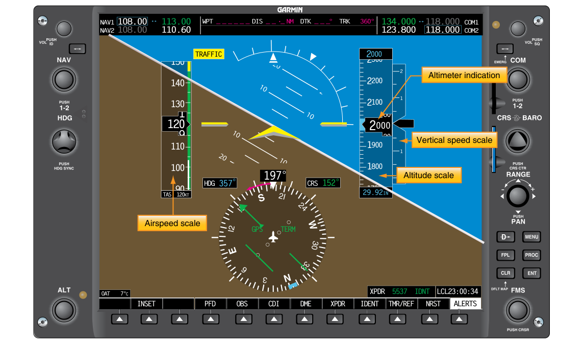
A typical glass PFD presents air-data information as moving tapes rather than rotating needles. Knowing the layout lets you scan efficiently during actual IMC.
Airspeed Tape (Left Side)
The airspeed tape scrolls vertically; the current speed is shown at the index mark (a fixed pointer in the center of the tape). Color-coded bands overlay the tape and correspond directly to the V-speed arcs you would see on a traditional airspeed indicator: white arc (flap operating range), green arc (normal operating range), yellow arc (caution/maneuvering), and red line (Vne). Many systems add a trend vector — a magenta or cyan line extending from the current speed bug that shows where speed will be in approximately six seconds at the current rate of change. This replaces the kinesthetic feel of the needle sweeping.
Altimeter Tape (Right Side)
Altitude appears on a vertically scrolling tape, typically in 20-foot increments with a larger digital readout in a box at the tape center. The barometric setting (kollsman window equivalent) is displayed as a digital readout — usually at the bottom of the tape — and is adjusted with a knob or softkey. This is a common trap: when you reset the baro setting after descending below the transition altitude, the altimeter tape snaps to the new value instantly; pilots scanning too quickly can misread the transition. Additionally, many PFDs display a Selected Altitude bug — a cyan or magenta chevron on the tape — showing the altitude pre-selected in the flight management system or altitude pre-selector. The PFD will alert you (often with a flashing annunciation) when approaching or deviating from the selected altitude.
Vertical Speed Indicator
VSI on a PFD appears as a narrow vertical scale on the inner edge of the altitude tape or as a separate small arc. Because the ADC computes VSI from the rate of pressure change rather than a mechanical capsule, the glass VSI has a much faster response — often called an Instantaneous Vertical Speed Indicator (IVSI) equivalent — and does not exhibit the traditional VSI lag. This is a critical exam point: the glass VSI leads rather than lags, meaning it may briefly over-indicate rate when you abruptly pitch the nose.
Attitude Display Integration
The ADC data feeds into the PFD alongside data from the Attitude and Heading Reference System (AHRS), which provides pitch, bank, and heading. Together they form the integrated PFD: the artificial horizon occupies the center of the screen, with the air-data tapes flanking it. The key instructional point is that these are two separate systems — a failed ADC does not necessarily corrupt the attitude display, and a failed AHRS does not kill the air-data tapes. Recognizing which system has failed determines which backup procedure to use.
ADC Failure Modes and Recognizing Them
Because the ADC is a digital processor, it performs continuous self-monitoring. Most certified units display a red X through the affected tape when the ADC detects an internal failure or loss of a required input. You may see a red X on the airspeed tape only (failed pitot line), on the altitude tape only (failed static line), or across all air-data tapes simultaneously (total ADC failure). In contrast, a pitot blockage with static port open will cause the airspeed indicator to freeze or drop toward zero, while the altitude tape continues to function. A static port blockage will freeze both altitude and VSI while airspeed continues to read (with increasing error as altitude changes). These failure signatures are the same as with traditional gauges — the glass cockpit simply makes the red X flag the failure more visibly.
Many glass-panel aircraft carry a backup standby instrument — often a small, self-contained analog or electronic unit — that draws directly from the pitot-static system independently of the ADC. Knowing how to cross-check the standby instrument and when to trust it over the PFD is a core IFR skill.
Key Numbers and Rules
- The ADC computes CAS, TAS, pressure altitude, density altitude, Mach, and VSI from pitot pressure, static pressure, and OAT.
- A red X through a tape on the PFD signals an ADC-detected failure for that parameter — do not attempt to read through a flagged display.
- Glass VSI typically behaves as an IVSI — faster response and may overshoot briefly during abrupt pitch changes; do not chase small VSI excursions.
- The baro setting on a glass PFD must still be set to 29.92 in. Hg above the transition altitude (18,000 ft MSL in the contiguous US) just as with traditional altimeters — this is 14 CFR and AIM-driven, not a glass-specific rule.
- Altimeter setting changes on a glass PFD take effect immediately and digitally — cross-check by verifying the altitude readout is within approximately 75 feet of field elevation before departure.
- Most systems display TAS as a supplemental readout (often near the top of the PFD or on an engine/systems page) — it is NOT the primary number used for traffic separation or ATC communications; always report IAS or CAS when asked for airspeed.
Why It Matters for IFR Flight
Under IMC, you have no outside visual references. Every altitude deviation and airspeed trend must be caught early from the PFD. A partial-panel scenario — whether caused by an ADC failure, a blocked pitot tube, or an AHRS upset — requires you to transition instantly to backup instruments and alternate procedures. The FAA's Instrument Flying Handbook emphasizes that glass-panel pilots must receive specific training in recognizing and managing these failures because the failure presentations differ subtly from traditional gauges.
Furthermore, automation complacency is a documented risk with glass cockpits. Because the PFD makes everything look clean and authoritative, pilots have historically trusted erroneous data longer than they would have trusted a visibly shaking needle. The discipline is to keep asking: do the airspeed, altitude, and attitude all agree with each other and with the flight profile I expect?
Common Test Traps
- ADC vs. AHRS failures are independent. A question may describe an attitude display failure and ask which instruments are also lost — the air-data tapes are NOT necessarily affected, because they come from the ADC, not the AHRS.
- Glass VSI leads, not lags. Traditional VSI has a 6–9 second lag; the glass IVSI-equivalent responds nearly instantly. Test questions sometimes present a scenario where you expect lag and must choose the correct instrument behavior.
- TAS is displayed but not reported to ATC. When ATC asks for your airspeed, give IAS. TAS displayed on the PFD is for planning, not position reporting.
- Baro setting rules are unchanged. Glass cockpits do not change the regulatory requirement to set 29.92 in. Hg at and above the transition altitude, or to set the local altimeter setting below it.
- Red X means stop using that tape. Some students think they can still read through a flagged display with caution. Under FAA guidance, a flagged instrument is unreliable and the pilot must use the standby instrument.