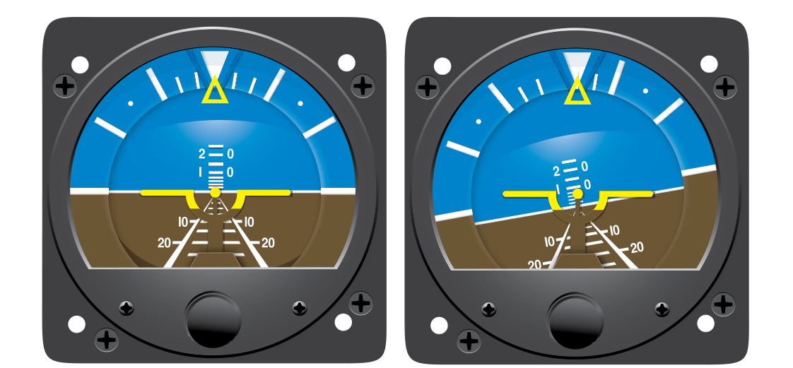
The attitude indicator (AI) — sometimes called an artificial horizon — is the centerpiece of the "basic T" instrument scan and arguably the most important reference a pilot uses during instrument flight. It provides an immediate, intuitive depiction of aircraft pitch and bank relative to the horizon. In clear air, a glance at the AI and a quick cross-check with the altimeter, heading indicator, and airspeed indicator is enough to keep an aircraft under control. But the attitude indicator is not perfect. Under specific conditions — prolonged turns and phases of acceleration or deceleration — it can display pitch and bank readings that simply are not accurate. A pilot who trusts the AI without understanding these errors can be misled at the worst possible moment.
This article explains exactly why these errors occur, how large they can be, what they look like in the cockpit, and how to detect and correct for them. This topic appears regularly on the FAA Instrument Rating knowledge test and is equally important for practical airmanship on every IFR flight.
How the Attitude Indicator Works
Most traditional attitude indicators are driven by a gyroscope — a rapidly spinning mass that resists changes in its orientation due to rigidity in space. The gyro rotor spins at thousands of RPM (typically driven by either a vacuum/pressure system or an electric motor), and its spin axis is maintained vertically by an erection mechanism. In vacuum-driven AI systems, small pendulous vanes detect the slight tilt of the gyro from true vertical and bleed air to one side or another, gently precessing the gyro back to upright. This erection system is what makes the AI self-correcting — but it is also the source of both types of errors discussed below.
Modern glass-panel displays use attitude and heading reference systems (AHRS), which rely on solid-state accelerometers, rate gyros, and magnetometers rather than a mechanical spinning gyro. AHRS units are largely immune to the classic gyroscopic errors described here, though they can have their own initialization and sensor-fusion errors. For the FAA knowledge test, the focus remains on gyroscopic AI errors, and understanding them clarifies why the underlying physics matter.
Acceleration Errors (False Pitch During Speed Changes)
The first major error category occurs during rapid acceleration or deceleration on a northerly or southerly heading — but more importantly, it occurs in the AI itself when the gyro erection system is fooled by inertial forces.
Here is the mechanism: the pendulous vanes in a vacuum-driven AI hang straight down under gravity alone. When the aircraft accelerates forward, inertia causes the vanes to swing rearward relative to the aircraft, exactly as a pendulum would if you pushed it forward. The erection system interprets this rearward swing as if the gyro were tilting nose-up, and it begins to precess the gyro in that direction. The result is a false nose-up indication on the AI during acceleration. Conversely, during a rapid deceleration (such as extending flaps or deploying spoilers), the vanes swing forward, and the AI erroneously shows a nose-down pitch.
In practice, this error builds slowly because the erection mechanism is intentionally sluggish (it only corrects about 2–3 degrees per minute to avoid over-correcting). A brief, sharp acceleration produces only a small error. However, a sustained power change combined with a pitch change — common during a climb entry — can introduce a noticeable false pitch reading. The practical rule: cross-check the AI with the altimeter and vertical speed indicator (VSI) during significant power or configuration changes, and do not fixate on the AI alone.
Turning Errors (The Graveyard Spiral Setup)
The second and more insidious category is turning errors, sometimes called the graveyard spiral error or leans-inducing error. These arise for the same reason — the erection mechanism is fooled — but the geometry is different.
During a prolonged, coordinated turn, the aircraft is banked continuously. The pendulous vanes now hang toward the low wing, because centrifugal force (a fictitious outward force in the rotating reference frame) pushes them outward and downward. The erection system interprets this as the gyro having drifted toward the high side, and it precesses the gyro toward the vertical of the banked aircraft rather than toward true vertical. After a turn of 180 degrees or more — such as a procedure turn or holding pattern entry — the gyro may have precessed enough that when the wings are leveled, the AI briefly shows a slight bank in the opposite direction from the turn just completed.
This is one of the key contributors to the leans: the pilot levels the wings using the AI, the aircraft is objectively wings-level, but the AI (and the pilot's vestibular system) says it is still slightly banked. The pilot then feels an overwhelming urge to re-bank toward the original turn. If the pilot acts on that urge, a gradual bank re-establishes, airspeed begins to increase as the nose drops in the bank, and without immediate correction the situation escalates into an uncontrolled spiral (graveyard spiral) — one of the leading causes of fatal IFR accidents in IMC.
The Rate-of-Erection Problem
Both errors are limited in magnitude partly because the erection rate is slow — typically 2–3 degrees per minute in a standard vacuum-driven system. However, even at that rate, a 45-second turn can introduce a 1–2 degree error, and after a 3-minute racetrack pattern, several degrees of accumulated error are plausible. More important than the absolute magnitude of the error is the direction and timing: the error peaks just as the pilot is returning to straight-and-level flight and needs the most accurate reference.
Why It Matters: Safety and the IMC Environment
In visual meteorological conditions (VMC), a pilot who feels the leans or notices an AI disagreement can simply look outside to confirm the actual horizon. In IMC, there is no outside reference. The pilot must resolve the conflict between instruments and vestibular sensation using logic and discipline alone. Spatial disorientation claims a disproportionate share of fatal general aviation accidents each year, and a large percentage of those involve loss of control in IMC.
Understanding AI errors gives a pilot the mental framework to say: "I just completed a 180-degree turn; the AI may be slightly off — I will confirm wings-level using the turn coordinator and heading indicator before trusting that reading." That pause and cross-check is what prevents the leans from becoming fatal.
Key Numbers and Rules
- Erection rate: approximately 2–3 degrees per minute for a vacuum-driven gyroscopic AI.
- Normal operating vacuum: typically 4.5–5.5 inches of mercury for most light aircraft AI systems; outside this range, gyro precession rates change and errors increase.
- Turning error onset: most pronounced during prolonged turns exceeding 180 degrees — typical during procedure turns, holding entries, and course reversals.
- Acceleration error direction: acceleration → false nose-up; deceleration → false nose-down.
- Turning error direction: after completing a prolonged turn in one direction, the AI may briefly show residual bank in the opposite direction when wings are leveled.
- AHRS immunity: solid-state AHRS systems do not suffer from pendulous vane errors; however, they can show initialization errors during power-up or after unusual attitudes.
Common Test Traps
- Confusing acceleration error direction: Students often mix up which way the AI errs. Remember — acceleration makes the AI lie nose-up, not nose-down. The vanes swing back, just like an unsecured object on your dashboard when you accelerate.
- Assuming the error is immediate and large: The erection mechanism is slow. The error accumulates gradually, meaning a quick burst of throttle causes only a tiny transient. The FAA tests whether you know the error is cumulative during sustained conditions.
- Thinking turning errors only matter in steep turns: Turning errors develop in any prolonged coordinated turn, including the standard-rate turns used in instrument procedures. You do not need an unusual attitude for the error to appear.
- Ignoring the role of vacuum system health: A marginal vacuum source causes the gyro to spin below its rated RPM, making the gyro less rigid and increasing susceptibility to all precession errors. The AI may still display normally at first glance while being significantly less reliable.
- Overlooking the leans as instrument-induced: Students sometimes think the leans are purely a vestibular phenomenon. In reality, a precessed AI actively reinforces the spatial disorientation by displaying a false bank, making it harder — not easier — to trust the instruments.
Memory Aid
A simple phrase to remember the direction of acceleration error: "ANDS" — Accelerate North Descend South (for the magnetic compass) … and Accelerate Nose-Up for the AI. For the AI specifically, just recall: "Gas gives nose-up, brakes give nose-down." This maps directly to the physics — accelerating pushes the vanes back, erection responds as if the nose lifted.
In the Cockpit: Practical Application
The best defense against AI errors is a disciplined cross-check scan. The FAA recommends centering your scan on the AI but making frequent excursions to the supporting instruments — particularly the turn coordinator, altimeter, vertical speed indicator, and airspeed indicator. If the AI shows wings-level but the turn coordinator shows a deflection, or if the altimeter is winding down while the AI shows level flight, believe the cluster of supporting instruments over the AI alone. This technique, sometimes called "believing the majority," is your primary protection against a precessed AI leading you astray. Develop the habit of checking the AI's miniature aircraft alignment against the pitch trim and power settings you expect for the current phase of flight, and never let a disagreement go uninvestigated.