Every time an airplane climbs away from the runway, it is exploiting one of the most elegant relationships in physics: the connection between a fluid's speed and its pressure. This relationship, first described by Swiss mathematician Daniel Bernoulli in the 18th century, sits at the heart of how wings generate lift. For a student pilot, understanding Bernoulli's Principle is not merely an academic exercise — it explains why your airplane's wing is shaped the way it is, why angle of attack matters so profoundly, and what is actually happening in the invisible air surrounding the aircraft every moment of flight.
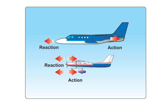
It is important to note from the start that lift is produced by a combination of factors, and no single principle tells the whole story. The FAA's Pilot's Handbook of Aeronautical Knowledge (PHAK) carefully explains that both Bernoulli's Principle and Newton's Third Law of Motion contribute to lift. This article focuses on the Bernoulli side of the equation, including how the Venturi effect demonstrates it and how airfoil designers put it to practical use.
Bernoulli's Principle: The Core Idea
Bernoulli's Principle states that within a steadily flowing fluid (liquid or gas), an increase in the fluid's velocity is accompanied by a decrease in its static pressure, and vice versa. In other words, faster-moving air exerts less static pressure than slower-moving air. This might seem counterintuitive — we often associate fast-moving things with more force — but it holds true for streamlined, non-turbulent flow and is consistently demonstrated in everyday aerodynamics.
To understand why, think about energy conservation. A fluid in motion carries two relevant types of energy: static pressure energy (the pressure it exerts on surrounding surfaces) and dynamic pressure energy (the energy of its motion). The total of these two remains essentially constant along a streamline. When the fluid is forced to move faster — because the passage it flows through narrows, for example — its dynamic pressure increases, so its static pressure must decrease to keep the total constant. This trade-off is the engine behind the Venturi effect and, ultimately, behind lift.
The Venturi Effect: Bernoulli Made Visible
A Venturi tube is a simple device that makes Bernoulli's Principle easy to observe. It is a pipe with a narrowed constriction in the middle. As air (or any fluid) flows through the tube and reaches the constriction, it must speed up because the same volume of air has to squeeze through a smaller cross-sectional area in the same amount of time — a consequence of the continuity principle. At that narrower section, velocity rises sharply and static pressure drops measurably. If you connected a pressure gauge to the constriction, it would read noticeably lower than gauges at the wider ends of the tube.
This is not just a laboratory curiosity. Early aircraft carburetors used a Venturi to draw fuel into the airstream — the low pressure at the throat of the Venturi literally sucked fuel in without any pump. More importantly for lift theory, the upper surface of a wing acts very much like the narrowed throat of a Venturi tube. The curved upper surface forces air to travel a longer, more constricted path between the wing and the free airstream above it, accelerating that air and lowering its pressure relative to the air beneath the wing.
Airfoil Shape and How It Exploits Bernoulli's Principle
An airfoil is the cross-sectional shape of a wing, and its design is deliberate. A typical cambered airfoil has a rounded, more convex upper surface and a flatter lower surface. When air approaches the leading edge and splits — some going over the top, some going beneath — the air traveling over the top must follow a longer curved path. The PHAK describes how this curvature accelerates the upper airflow, lowering the static pressure above the wing. Meanwhile, air traveling beneath the wing flows along a flatter, more direct path, moving more slowly and maintaining higher static pressure.
The result is a pressure differential: higher pressure below the wing, lower pressure above. Nature drives fluids from high pressure toward low pressure, so this differential produces a net force pushing (or more precisely, drawing) the wing upward. That force is lift. The greater the pressure differential, the greater the lift generated — up to the limits imposed by the wing's design and the onset of airflow separation (a stall).
Camber — the curvature built into the airfoil — is the primary geometric tool designers use to exploit Bernoulli's Principle. A highly cambered wing generates more lift at lower speeds, which is why high-lift devices like flaps effectively increase camber when extended. A symmetrical airfoil (equal curvature top and bottom) generates no lift at zero angle of attack because there is no pressure differential at that condition — but it can still generate lift when pitched to a positive angle of attack, where the geometry again forces upper-surface air to accelerate.
Angle of Attack: Amplifying the Effect
While airfoil shape creates a baseline pressure differential, angle of attack (AOA) — the angle between the chord line of the wing and the relative wind — powerfully modulates how much lift is produced. Increasing AOA directs more airflow across the curved upper surface and increases the effective curvature the air must follow, further accelerating upper-surface airflow and deepening the pressure differential. This is why pulling back on the controls at a given airspeed increases lift.
However, AOA has a critical upper limit. If AOA increases beyond the critical angle of attack (typically around 15 to 20 degrees for most general aviation airfoils, though the precise value is specific to each design), the airflow can no longer smoothly follow the upper surface. It separates from the wing, the smooth pressure differential collapses, and lift drops dramatically. This is a stall — and it is entirely an angle-of-attack phenomenon, not a speed phenomenon per se. A wing can stall at any airspeed if the critical AOA is exceeded.
Why It Matters: Real-World and Safety Implications
Understanding the Bernoulli-based pressure differential is not just theory — it has direct safety implications throughout your flying career. Recognizing that lift depends on the pressure differential helps explain why flying slower requires a higher AOA to maintain the same lift (you are compensating for reduced dynamic pressure by increasing the wing's effective contribution). It explains why a heavily loaded aircraft requires more speed or AOA to fly — more lift must be generated to support greater weight. And it is the reason that stall speed increases in a steep turn: the vertical component of lift must support the full weight while the wing is banked, requiring more total lift, which demands more AOA at any given speed, bringing the critical AOA closer.
The Venturi effect also directly affects your instruments. The airspeed indicator works by comparing ram air pressure (from the pitot tube) to static pressure. The altimeter and vertical speed indicator rely solely on static pressure. If your static port — which samples the ambient static pressure — is blocked, these instruments can give dangerously misleading readings because the Bernoulli relationship between static and dynamic pressure is the foundation of how these devices function.
Key Numbers and Rules
- Pressure differential drives lift: Lower pressure above the wing and higher pressure below produces the net upward force called lift.
- Critical angle of attack: Most general aviation airfoils stall somewhere in the range of 15–20 degrees AOA; the exact value is airfoil-specific and must be treated as a design limit, not a general rule.
- Lift equation components: Lift = CL × ½ρV² × S, where CL is the coefficient of lift (influenced by AOA and camber), ρ is air density, V is velocity, and S is wing area. Bernoulli's principle underlies the pressure difference that CL represents.
- Flaps increase camber: Extending flaps increases wing camber and area, generating more lift (and drag) at lower speeds — directly exploiting the Bernoulli pressure differential.
- Symmetrical airfoils: Generate zero lift at zero AOA but can produce lift at positive AOA, commonly used in aerobatic aircraft and helicopter rotor blades.
- Venturi in carburetors: The low-pressure throat of the Venturi draws fuel into the airstream; venturi-related carburetor icing is a tested topic because the pressure drop also causes a temperature drop.
Memory Aid
"Fast air, low pressure — slow air, high pressure." This simple phrase encapsulates Bernoulli's Principle in a form you can recall instantly. When you see a curved upper wing surface, remind yourself: air speeds up over the curve (like squeezing through the throat of a Venturi), pressure drops, and the higher-pressure air below pushes the wing upward. Fast = low. Slow = high. The difference = lift.
Common Test Traps
- Confusing dynamic and static pressure: Bernoulli's Principle involves static pressure decreasing as velocity increases — not total pressure. The FAA knowledge test may ask you to distinguish between static, dynamic, and total pressure; keep these definitions clear.
- Thinking stall is only about speed: A stall occurs when the critical angle of attack is exceeded, not when a specific airspeed is reached. You can stall at full power and high speed in a steep turn — a common test scenario.
- Assuming only Bernoulli explains lift: The FAA explicitly acknowledges that Newton's Third Law (the wing deflecting air downward creates an equal and opposite upward reaction) also contributes to lift. Claiming lift is purely a Bernoulli phenomenon is an oversimplification the test may probe.
- Forgetting that flaps increase both lift and drag: Students often remember the lift increase from greater camber but forget the significant drag increase, which lowers best glide speed and affects climb performance.
- Misreading the Venturi carburetor icing question: The pressure drop at the Venturi throat causes a temperature drop, which can cause carburetor icing even when outside air temperatures are well above freezing — often in the 20–70°F range with visible moisture. This is a frequently tested trap because pilots assume icing only happens in freezing temperatures.