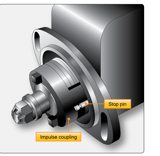
Starting a reciprocating aircraft engine presents a fundamental challenge: the engine cranks slowly, yet the magneto needs to spin fast enough to generate a strong spark at precisely the right moment. An impulse coupling solves both problems simultaneously by temporarily storing energy in a wound spring and releasing it in a sudden snap — producing both a high-intensity spark and an automatically retarded ignition timing during start. Once the engine reaches operating speed, the impulse coupling disengages and the magneto runs directly off the engine drive, restoring normal advance timing. For Aviation Maintenance Technicians preparing for the FAA Powerplant knowledge test and oral exams, a thorough grasp of impulse coupling design, operation, and inspection procedures is indispensable.
Impulse couplings are typically installed on one magneto only — almost always the left magneto on a dual-magneto system — because a single retarded, energized spark is sufficient to fire the engine during start. The right magneto on the same engine generally uses a retard breaker or is simply grounded out during start. Some high-powered or twin-engine installations differ, but the left-impulse convention is so common that the FAA knowledge test regularly tests it.
How the Impulse Coupling Works
The impulse coupling sits between the engine accessory drive and the rotating magnet of the magneto. It consists of three primary components: a flyweight assembly, a coil spring, and a body shell (hub) that connects to the drive gear. When the engine is cranked slowly at starter speed, the flyweights are held latched inward by spring engagement (a mechanical latch, not simply gravity), keeping them in this position at low rotational speed. In their inward (latched) position, they catch on a stop pin attached to the magneto housing.
Here is the sequence in detail. As the engine crankshaft turns, the coupling body rotates and winds the coil spring tighter against the stationary magnet assembly (which is held temporarily by the flyweight-stop pin engagement). This wind-up continues through crankshaft rotation, storing energy, until the winding reaches the release point — timed to correspond with a slightly retarded piston position — at which point the spring releases suddenly, snapping the magnet rotor through its E-gap position at high angular velocity. This rapid rotation induces a high-voltage spark of greater intensity than a slow crank alone could produce. Because the release occurs a few degrees after top dead center (or at top dead center depending on engine type), the timing is retarded to prevent a kickback that could injure the starter or the person hand-propping the engine.
Once the engine fires and accelerates, centrifugal force throws the flyweights outward, with the exact RPM threshold depending on the specific coupling design and specified in the applicable manufacturer's maintenance manual. In the outward position, the flyweights clear the stop pin, allowing the coupling body and magnet assembly to rotate together as a solid unit. The spring is no longer wound or released — it simply transmits torque directly. From this point forward, the magneto operates at its designed advance timing, driven continuously by the engine at a 1:1 or stepped gear ratio.
Why Impulse Couplings Matter
Without an impulse coupling (or equivalent starting aid), two problems arise during a hand-crank or electric-start attempt. First, the magneto spins too slowly to reach its E-gap position — the precise rotor angle at which magnetic flux collapse is most rapid and therefore spark voltage is highest — with sufficient speed to produce a reliable spark. The result is a weak or missing ignition event. Second, if the timing is not retarded, a spark occurring before top dead center during slow cranking can drive the piston backward violently, causing engine kickback — a dangerous event that can break a starter, shear a crankshaft, or injure a person hand-propping.
The impulse coupling elegantly addresses both problems without any pilot or technician input — it is entirely automatic and mechanical. This simplicity is also why it is robust and long-lived when properly maintained. However, when it fails, it fails in characteristic ways that must be recognized.
Key Numbers and Rules
- Snap release speed: The impulse coupling releases the magnet rotor through its E-gap at a speed far greater than starter cranking speed, though FAA-H-8083-32 does not publish a fixed cranking RPM figure — actual cranking speed varies by engine and starter type.
- Flyweight engagement speed: Flyweights remain latched inward at low speed and fly outward (disengaged) once centrifugal force overcomes the latch at a design-specific RPM threshold, which should be verified in the applicable manufacturer's maintenance manual.
- Retard amount: Timing during the impulse-coupled start is typically retarded to top dead center (TDC) or slightly after, compared to the normal advance timing (commonly around 20–25° BTDC) specified by the engine manufacturer for running operation.
- Left magneto convention: The impulse coupling is installed on the left magneto in most single-engine and light twin installations.
- Inspection interval: Impulse couplings are typically inspected at each magneto inspection interval — commonly every 500 hours per many magneto manufacturers' service documents (e.g., Slick/Bendix), but this is not a universal FAA-mandated figure and must always be verified against the engine manufacturer's Instructions for Continued Airworthiness (ICA) and the magneto manufacturer's overhaul manual.
- Replacement: Impulse couplings that exhibit wear, cracked springs, or erratic snap action must be replaced as an assembly; field repair of internal components is not authorized by most manufacturers.
Inspection Procedures
Inspecting an impulse coupling is part of a thorough magneto inspection. The technician begins by removing the magneto from the engine per the applicable maintenance manual, ensuring the magneto switch is OFF and the primary circuit is grounded to prevent accidental firing during handling. The impulse coupling is then examined both visually and functionally.
Visual Inspection
With the coupling accessible, inspect for cracks, corrosion, worn flyweight pivots, and chipped or broken stop pins. The coil spring should show no distortion, broken coils, or loss of tension. Flyweight ears must not be deformed. The body shell should be free of cracks at the spring attachment point, which is a high-stress location. Any metallic debris or shavings in the coupling area indicate internal wear and require further investigation and likely replacement.
Functional (Snap) Check
Hold the magneto body firmly and rotate the coupling drive hub slowly by hand in the direction of normal rotation. You should feel and hear the flyweights latch, the spring wind up with increasing resistance, and then a clean, crisp snap as the spring releases and the rotor kicks through. A weak or mushy snap indicates a fatigued spring. No snap at all may indicate a broken spring or a flyweight that is not latching. Multiple snaps or grinding during the wind-up indicates worn flyweights or a damaged stop pin. The snap should be clean and decisive every time.
Flyweight Check
Verify that flyweights pivot freely on their pins and return to the inward (latched) position under spring engagement when the coupling is stationary. Flyweights that stick outward will prevent latching and mean the coupling never engages — the engine will be hard or impossible to start. Flyweights that stick inward will prevent disengagement at operating speed, causing the magneto timing to remain retarded and reducing engine power and efficiency, often causing rough running and high fuel consumption.
Common Test Traps
- Which magneto gets the impulse coupling? The FAA test frequently asks this. The answer is the left magneto. Do not confuse this with the right magneto or assume both are impulse-coupled in a standard installation.
- What does the impulse coupling actually do to timing? It retards the spark during start — it does not advance it. Students sometimes confuse retard with advance because the snap makes the spark seem more energetic; the key point is the spark fires later (at or near TDC) to prevent kickback.
- Weak snap vs. no snap: A weak snap means a fatigued spring still capable of releasing; no snap at all likely means the flyweights are not latching or the spring is broken. Both are unairworthy conditions, but the failure mode differs.
- Stuck flyweights — inward vs. outward: Flyweights stuck inward mean the coupling never disengages; timing stays retarded at cruise — the engine runs rough and produces less power. Flyweights stuck outward mean the coupling never engages at all — hard starting or no-start condition.
- Field repair authorization: Do not be tempted to repair individual components of an impulse coupling unless the manufacturer's data specifically authorizes it. In most cases, a defective coupling is replaced as a complete assembly, and that is the testable answer.
Practical Takeaways for the AMT
The impulse coupling is one of the most mechanically elegant solutions in reciprocating engine ignition design. Its entirely automatic operation requires no pilot or technician intervention during normal use, yet it dramatically improves startability and prevents kickback. Because it operates every time the engine is started, cumulative wear is real — a high-utilization training aircraft may rack up thousands of start cycles in a single year. Building a habit of listening for the characteristic snap during run-up checks and flagging any unusual resistance or absence of snap during magneto removal is the mark of a thorough AMT. Keeping current with the engine and magneto manufacturer's ICA, inspecting at prescribed intervals, and replacing rather than improvising repairs will keep this critical component reliable throughout its service life.