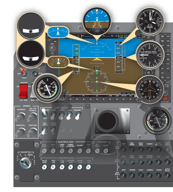
Walk into most modern flight training aircraft and you will find a large, bright screen dominating the instrument panel where a cluster of round gauges used to live. That screen is the Primary Flight Display (PFD), the centerpiece of a glass cockpit avionics suite. Yet many training fleets still operate with the classic arrangement of six individual analog instruments, affectionately called the six-pack. The FAA knowledge test and practical exam expect you to understand both layouts — how they work, what data they show, and what happens when either one fails. More importantly, understanding both philosophies makes you a safer, more adaptable pilot regardless of which cockpit you climb into.
This article walks through the traditional six-pack, explains how the PFD reorganizes and enhances that same information, covers the failure modes unique to each system, and highlights the exam-critical details you need to know.
The Traditional Six-Pack
The six-pack is an arrangement of six analog flight instruments grouped in two columns of three on the instrument panel. The layout follows a deliberately logical pattern that pilots and engineers settled on over decades of experience. From top-left to bottom-right, the instruments are typically arranged as follows:
- Airspeed Indicator (ASI) — top left
- Attitude Indicator (AI) — top center
- Altimeter — top right
- Turn Coordinator — bottom left
- Heading Indicator (Directional Gyro) — bottom center
- Vertical Speed Indicator (VSI) — bottom right
The top row is sometimes called the primary instrument cross-check triangle: airspeed, attitude, and altitude. The bottom row provides supporting navigation and trend information. This layout follows the widely taught "basic T" scan pattern, with the heading indicator placed under the attitude indicator to reinforce the pilot's instrument scan.
How Each Instrument Works
Three of the six instruments rely on the pitot-static system. The airspeed indicator compares ram air pressure from the pitot tube against static pressure from the static port; the pressure difference drives a diaphragm that moves the needle. The altimeter uses only static pressure, expanding aneroid wafers as static pressure drops with altitude. The VSI also uses static pressure but measures the rate of change through a calibrated leak — it lags several seconds behind actual climbs and descents.
The remaining three instruments are gyroscopic. The attitude indicator and heading indicator use rigidly spinning gyroscopes that resist precession to maintain a fixed orientation in space. They are driven either by a vacuum (suction) pump or an electric motor. The turn coordinator uses a gyroscope mounted on a canted axis to sense both roll rate and yaw rate, and its inclinometer ball (the slip/skid indicator) is a simple, fluid-filled curved tube that responds to lateral acceleration — no gyro needed.
Understanding the power source of each instrument is critical for failure analysis. Vacuum-driven gyros typically include the attitude indicator and heading indicator. Electric gyros or electronic sensors often power the turn coordinator. The pitot-static instruments are passive — they need no electrical or pneumatic power, only unobstructed ports.
The Glass Cockpit Primary Flight Display
A PFD replaces all six analog instruments — and typically adds several more data sources — on a single high-resolution color display, usually between 7 and 10 inches wide. The Garmin G1000 is the most common training-aircraft example, but Avidyne, Dynon, and Garmin G3X systems follow similar design philosophies. The FAA's Pilot's Handbook of Aeronautical Knowledge (PHAK) describes PFDs as integrating data from Air Data Computers (ADC) and Attitude and Heading Reference Systems (AHRS) to generate the displayed information.
The ADC processes pitot and static inputs digitally, computing airspeed, altitude, and vertical speed with greater precision than mechanical diaphragms allow. The AHRS uses solid-state accelerometers and rate gyroscopes (micro-electromechanical sensors, or MEMS) along with magnetometers to determine aircraft attitude and heading. Because there are no spinning mechanical gyroscopes inside a modern AHRS, it suffers far less from precession errors and does not require a vacuum pump.
Layout of the PFD
Despite replacing analog gauges, the PFD deliberately preserves spatial logic that pilots expect. On a typical G1000 PFD:
- A large attitude sphere dominates the center — blue above the horizon, brown below.
- An airspeed tape scrolls vertically on the left side, with color-coded arcs showing flap operating range (white), normal operating range (green), caution range (yellow), and never-exceed speed (red line).
- An altitude tape scrolls on the right, with the current barometric setting displayed nearby.
- A vertical speed indicator appears as a vertical scale to the far right of the altitude tape.
- A horizontal situation indicator (HSI) — a combined heading indicator and navigation display — sits at the bottom of the attitude sphere.
- A slip/skid indicator appears as a small rectangle at the base of the attitude display, replacing the inclinometer ball.
This geography mirrors the six-pack spatially: airspeed is still on the left, altitude on the right, attitude in the center. The mental transition is far easier than it might appear at first glance.
Additional Data the PFD Provides
Beyond replicating the six-pack, a PFD typically integrates data that would have required separate instruments or radio receivers in a traditional cockpit. These commonly include: autopilot status and flight director command bars, navigation course deviation (ILS localizer and glideslope), GPS track and cross-track error, outside air temperature, density altitude, wind speed and direction, and traffic or terrain alerts. All of this situational awareness data is presented in a logically organized, color-coded format that reduces the need to scan across multiple instruments or switch radio frequencies to read a morse code identifier.
Why This Matters for Safety and the Knowledge Test
The FAA emphasizes that understanding instrument failure modes is not optional — it is a fundamental safety skill. The two systems fail in very different ways, and a pilot who does not recognize a failure may continue flying on bad data until the situation becomes dangerous.
In a traditional six-pack aircraft, a vacuum pump failure silently removes the attitude indicator and heading indicator. The airspeed indicator, altimeter, and VSI continue working normally, as does the electric turn coordinator. A pilot trained to recognize this scenario can switch to partial-panel flying, using the turn coordinator, altimeter, and ASI to maintain aircraft control until landing. Because the failed gyros may continue to show plausible-but-wrong indications for several minutes as they slowly spin down, recognizing the failure quickly is essential.
In a glass cockpit, an AHRS failure removes attitude and heading data from the PFD. The ADC continues to supply airspeed, altitude, and vertical speed. Most glass-cockpit training aircraft carry a backup analog attitude indicator — often electrically powered as a standby — precisely because of this dependency. A display unit failure (the screen going dark) is different from an AHRS failure: the underlying sensors may still be working and the data can sometimes be accessed via the MFD (Multi-Function Display) or a reversionary mode. Knowing how to activate reversionary mode (often a single button press) is exam and checkride material.
A pitot tube blockage affects airspeed indication on both system types identically — the ASI or airspeed tape will give erroneous readings, particularly dangerous in IMC or at night when visual cues are absent. A static port blockage similarly affects altimeter, ASI, and VSI on both platforms. The pitot heat system helps prevent ice blockage, and the alternate static source provides a workaround for a blocked static port.
Key Numbers and Rules
- Airspeed color arcs: White arc = flap operating range (VS0 to VFE); Green arc = normal operating range (VS1 to VNO); Yellow arc = caution range (VNO to VNE); Red line = VNE (never exceed).
- Altimeter setting: Must be set to the current reported altimeter setting of a station along the route within 100 nautical miles of the aircraft, when available, per 14 CFR 91.121 and AIM guidance; standard 29.92 in Hg is used at and above 18,000 ft MSL.
- Heading indicator: Traditional heading indicators precess and must be aligned to the magnetic compass every 15 minutes approximately; AHRS-based heading on a PFD is continuously corrected by the magnetometer and does not require manual realignment.
- VSI lag: The traditional VSI lags actual vertical speed by a few seconds (commonly cited as up to about 6 seconds); the instantaneous VSI trend vector on some PFDs provides near-real-time rate data.
- Backup instruments: 14 CFR Part 91 and FAA guidance strongly recommend (and for IFR flight often require) standby airspeed, attitude, and altimeter instruments in glass-cockpit aircraft.
Common Test Traps
- Vacuum failure is silent. The FAA frequently tests whether students know that a vacuum pump failure will NOT trigger a cockpit warning in many light aircraft — the instruments simply slow down and eventually show incorrect data. Watch for a question asking which instruments are affected by vacuum failure: attitude indicator and heading indicator, NOT the turn coordinator (usually electric) or pitot-static instruments.
- The turn coordinator shows roll, not bank angle. Students confuse the turn coordinator with the attitude indicator. The turn coordinator's miniature airplane shows rate of turn (standard rate = 3°/second), not the precise bank angle. On a PFD, the attitude sphere displays actual bank angle directly.
- Blocked static port affects three instruments. A blocked static port causes errors in the altimeter, VSI, AND airspeed indicator — not just the altimeter. Students often forget the ASI is affected because it compares ram air to static pressure.
- Gyroscopic precession on traditional heading indicators. The heading indicator must be periodically realigned to the magnetic compass. A question might describe a heading indicator drifting and ask the cause — the answer is precession, not compass error or wind.
- AHRS is not the same as GPS. Students sometimes assume that glass cockpit attitude comes from GPS. The AHRS provides attitude and heading; the GPS provides position and ground speed. Both can fail independently. GPS failure does not cause attitude indicator failure on a PFD.
Whether you train on six steam gauges or a full glass suite, the underlying principles of flight instrument operation remain identical. Mastering both systems — their data sources, their failure modes, and their cockpit layout — makes you a more versatile pilot and a much safer one. The glass cockpit is a powerful tool, but it rewards the pilot who understands exactly what is generating each number on the screen.