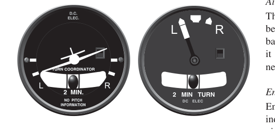
Every cockpit contains at least one instrument dedicated entirely to keeping your turns safe and coordinated. The turn coordinator — paired with its companion, the inclinometer ball — gives you two separate but complementary pieces of information: how fast you are turning and whether your rudder input matches your bank. Together, these two instruments form one of the most important tools in instrument and visual flight, and they appear on nearly every FAA Private Pilot knowledge test.
Understanding what each display actually measures, how the underlying gyroscope works, and what different ball and needle positions tell you is not just a test-prep exercise. Misreading these instruments contributes to the classic graveyard spiral and loss of control accidents that kill pilots every year. If you commit the mechanics and interpretation to memory, you will fly safer from day one.
How the Turn Coordinator Works
The turn coordinator houses a rate gyroscope — a spinning gyro whose gimbal is canted (tilted) approximately 30 degrees from the horizontal. This canted orientation allows the gyro to sense both rate of roll (how quickly the bank angle is changing) and rate of turn (how fast the aircraft is actually changing heading). This dual sensitivity is what makes the turn coordinator more useful than the older turn-and-slip indicator, which used a vertically mounted gyro and sensed only rate of turn.
The output of the gyro moves a small silhouette of an airplane on the instrument face. When you bank right, the miniature airplane's right wing dips; when you bank left, the left wing dips. The instrument is not showing you bank angle — it is showing you rate information. A common student mistake is to treat the miniature airplane like an attitude indicator and try to read pitch or precise bank angle from it. You cannot. What it accurately reflects is how rapidly you are rolling into or maintaining a turn.
Standard Rate Turn
Most turn coordinators have two index marks on each side, often labeled with an L and R. When the miniature airplane's wing aligns with the outer index mark, you are flying a standard rate turn, defined as a turn of exactly 3 degrees per second. At a standard rate, a complete 360-degree turn takes 2 minutes. A 180-degree turn takes 1 minute. These numbers are directly testable on the FAA knowledge exam.
The bank angle required to achieve a standard rate turn depends on your airspeed. A rough rule of thumb: divide your airspeed in knots by 10, then add 7 to get the approximate bank angle in degrees. At 90 knots, for example, 9 + 7 = 16 degrees of bank will produce a standard rate turn. At 120 knots, you need about 19 degrees. This is an approximation used for planning timed turns, and the result gets less precise at higher speeds. This is why faster aircraft require steeper banks to achieve the same 3-degrees-per-second rate.
The Inclinometer: Reading the Ball
The inclinometer is the small curved glass tube filled with liquid and containing a dark ball (sometimes called the slip-skid ball or simply the ball). Unlike the gyroscopic turn indicator, the inclinometer is a purely inertial device — it has no moving mechanical parts other than the ball itself. The ball responds to the balance of centrifugal and gravitational forces acting on it. It tells you one thing: whether your rudder use is coordinated with your aileron input.
Centered Ball — Coordinated Flight
When the ball rests exactly in the center of the tube, between the two reference marks, the forces on the aircraft are balanced laterally. The lift vector is aligned with the aircraft's direction of turn, and there is no net sideways force pushing the ball off center. This is coordinated flight. You can be in level flight, in a climb, or in a banked turn — coordinated means the ball is centered regardless of pitch or bank attitude.
Ball Out to the Outside — Skidding Turn
If the ball moves toward the outside of the turn (for example, you are banked left but the ball slides to the right), you are in a skid. A skid means you have too much rudder applied relative to the bank angle — either excessive rudder in the direction of the turn, or too little bank for the rate of turn the rudder is demanding. In a skid, the aircraft's tail is swinging outward. The nose is yawing faster than the bank warrants. In the worst case, a skidding turn at low altitude and slow airspeed creates the dangerous condition where the inside (lower) wing can exceed its critical angle of attack and stall, leading to an uncoordinated spin toward the ground.
Ball Out to the Inside — Slipping Turn
If the ball moves toward the inside of the turn (banked left, ball also moves left), you are in a slip. A slip means you have too much bank for the amount of rudder applied, or you are holding opposite (top) rudder against the turn. In a slip, the aircraft is moving somewhat sideways through the air, with the nose pointing across the flight path. Slips have a practical use — a forward slip deliberately increases drag to lose altitude without increasing airspeed on approach — but an unintentional slip in the traffic pattern is a sign of poor coordination and can mask airspeed decay.
The Memory Shortcut: Step on the Ball
Memory aid
"Step on the ball" is the universal correction reminder for the inclinometer. Whichever side the ball has rolled to, apply rudder pressure on that same side (press with your foot on the side where the ball is). If the ball is left, press left rudder. If the ball is right, press right rudder. This input corrects the yaw imbalance and re-centers the ball. The mnemonic captures a simple truth: the ball shows you exactly where to push.
Why It Matters: Real-World and Safety Significance
The turn coordinator and ball take on life-or-death importance in several specific scenarios:
- Inadvertent IMC: When a VFR pilot accidentally enters clouds without an attitude indicator (or with one that has failed), the turn coordinator becomes the primary source of turning information. The classic instrument-failure scan places the turn coordinator at the center of partial-panel navigation.
- Base-to-final turn: This is statistically one of the most dangerous moments in the pattern. Pilots often apply too much rudder to "hurry" the turn onto final approach, creating a skidding turn close to the ground at slow airspeed — exactly the setup for an uncoordinated stall-spin accident.
- Engine failure in a multi-engine aircraft: Asymmetric thrust creates strong yawing forces. The ball can shift dramatically, indicating to the pilot the amount of rudder needed to maintain coordinated flight on one engine.
- Spiral dive recognition: A pilot in a graveyard spiral may feel no unusual G-forces because the turn is coordinated, yet be losing altitude rapidly. Recognizing the high rate of turn on the turn coordinator — even though the ball is centered — is the cue to level wings and reduce power.
Key Numbers and Rules
- Standard rate turn: 3 degrees per second
- Time for 360° at standard rate: 2 minutes
- Time for 180° at standard rate: 1 minute
- Gyro type in turn coordinator: Rate gyroscope, canted ~30° to sense both roll rate and turn rate
- Inclinometer type: Inertial (no gyro), liquid-filled curved tube
- Ball centered = coordinated flight (balanced lateral forces)
- Ball to outside of turn = skid (too much rudder relative to bank angle)
- Ball to inside of turn = slip (too much bank, insufficient rudder)
- Power source: Turn coordinators are typically electrically powered, making them useful as a backup when vacuum system failures disable the attitude indicator and directional gyro
Common Test Traps
- Confusing the turn coordinator with an attitude indicator. The miniature airplane on the turn coordinator does NOT show bank angle. It shows rate of turn and rate of roll only. The attitude indicator (AI) shows actual pitch and bank attitude. Many students mix these up on the written exam.
- Misidentifying skid vs. slip. The test will describe a turn and a ball position and ask which is occurring. Remember: ball to the outside = skid; ball to the inside = slip. Draw a mental picture of the ball's position relative to the direction of bank every time.
- Forgetting the 2-minute rule. FAA test questions frequently ask how long a standard rate turn takes for a full 360 degrees. The answer is always 2 minutes regardless of bank angle or airspeed, as long as the turn is maintained at standard rate (3°/sec).
- Assuming a coordinated turn is always safe. A spiral dive can be fully coordinated (ball centered) while the aircraft descends steeply. The turn coordinator shows you rate, not whether the maneuver is appropriate for the situation. Always cross-check altitude and airspeed.
- Overlooking the electrical power dependency. Because the turn coordinator is electrically driven (not vacuum), a vacuum failure that kills the AI and DI does NOT kill the turn coordinator. Conversely, an electrical failure does kill the turn coordinator. Knowing which instruments fail under which system failure is a classic multi-question cluster on the exam.
Mastering the turn coordinator and inclinometer ball means understanding that two separate instruments share one housing, each measuring something entirely different. The gyro-driven needle tells you how fast you are turning; the gravity-and-inertia ball tells you whether you are doing it in balance. Together they give you the two pieces of coordination information you need to keep every turn safe — on a clear afternoon and, more critically, when the clouds close in around you.