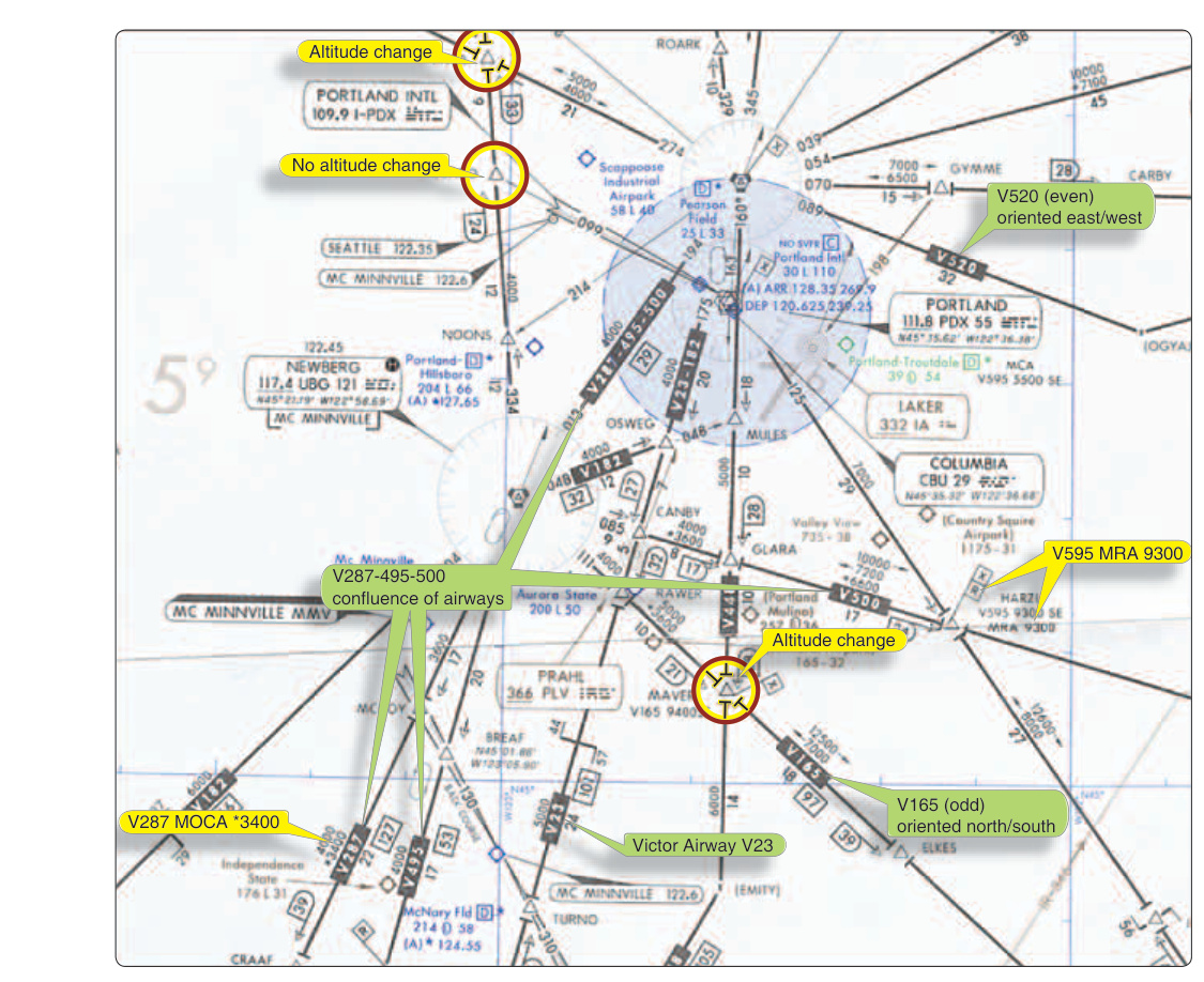
If you have ever watched an airliner's cleared route scroll across a dispatch sheet or listened to a clearance delivered over the radio, you have almost certainly heard "Victor" airways — designations like V-23 or V-105 that thread across the country connecting radio navaids. These airways are the highways of instrument flight below 18,000 feet mean sea level (MSL), and the FAA's Enroute Low Altitude (EL) chart is the map that depicts them. For an instrument-rated pilot, reading this chart fluently is as fundamental as reading a road map is to a driver. Understanding every line, number, and symbol will both prepare you for the FAA Instrument Rating knowledge test and keep you oriented, legal, and safe on your first IFR cross-country.
The Enroute Low Altitude chart is published by the FAA Aeronautical Information Services (and historically by NOAA's National Aeronautical Charting Office) on a regular 56-day cycle, the same cycle that governs instrument approach plates and other official IFR charts. The chart covers the contiguous United States in a series of panels and uses a Lambert Conformal Conic projection, which makes straight lines on the chart closely approximate great-circle routes — ideal for navigation over long distances.
What Victor Airways Are and How They Are Defined
Victor airways — formally called VOR Federal Airways — are corridors of airspace defined by VHF Omnidirectional Range (VOR) stations and associated navigation fixes. Each airway extends 4 nautical miles on each side of the centerline near the navaid, for a nominal width of 8 nautical miles. However, that width is not uniform along the entire segment — beyond a certain distance from the defining VOR, the protected width expands as the navaid's course guidance becomes less precise with distance, per the airway's designated service volume. This protected obstacle clearance area is what the FAA uses to guarantee that an aircraft flying the centerline with normal navigation accuracy will remain clear of terrain and obstacles, provided it flies at or above the Minimum Enroute Altitude (MEA).
Vertically, Victor airways begin at 1,200 feet AGL (or higher if terrain requires) and extend up to but not including 18,000 feet MSL. The airspace at and above 18,000 feet MSL belongs to Class A, where the Jet Route system (J-routes) takes over. Below 18,000 feet MSL, Victor airways are Class E airspace when the aircraft is operating under an IFR clearance.
Each airway is identified by the letter V followed by a number, printed in blue on the chart alongside the blue line that traces the airway's centerline between navaids. Where two or more airways share the same segment, their designations are listed together, such as "V-25-105." The magnetic course along each segment is printed on both sides of the centerline — one number for each direction of flight — allowing you to immediately verify whether your assigned course matches the charted bearing.
Key Altitudes Shown on the Chart
Several critical altitudes appear alongside each airway segment, and confusing them is one of the most common mistakes on the knowledge test.
- MEA (Minimum Enroute Altitude): The lowest published altitude for a route segment that guarantees both obstacle clearance and acceptable navigation signal reception from the defining NAVAID. It is the most prominently displayed altitude on the airway and is the altitude you are typically assigned or may request. In mountainous terrain the MEA can climb dramatically.
- MOCA (Minimum Obstruction Clearance Altitude): Provides the same obstacle clearance as the MEA but guarantees VOR signal reception only within 22 nm of the VOR. It is displayed on the chart with an asterisk (e.g., *3,400). You may fly at the MOCA only when within 22 nm of the VOR — outside that range you must be at the MEA.
- MAA (Maximum Authorized Altitude): The highest usable altitude for a given segment, above which the airway structure is no longer reliable due to signal overlap or interference. It is printed with a flag symbol. MAAs are relatively rare but tested.
- MRA (Minimum Reception Altitude): The lowest altitude at which an off-route intersection can be identified using the specified VOR or other NAVAID. Shown with an "R" flag.
- MCA (Minimum Crossing Altitude): The lowest altitude at which an aircraft may cross a fix when proceeding in a specific direction. It applies when the MEA beyond the fix is higher than the MEA before the fix, requiring the aircraft to begin climbing before reaching the fix. Shown with an "X" flag.
Navaids, Intersections, and Fixes
VOR stations are depicted as compass-rose symbols (a hexagon with tick marks) at which airways begin, end, or change direction. Each VOR box printed on the chart shows the station name, three-letter identifier, frequency, Morse code ID, and a channel number for TACAN-equipped aircraft. If the station also has DME capability, a small "D" or the letters "VORTAC" or "VOR/DME" will appear. This matters operationally because certain MEAs and procedures require DME capability.
Named intersections — five-letter identifiers like HAARP or BOSSS — mark points along airways that are defined by radials crossing from one or more VORs, or by DME distance from a VOR. They appear as small triangles on the chart. Intersections serve as reporting points, clearance limit points, and the boundaries between different altitude segments. GPS-defined waypoints may also appear on newer chart editions as airways increasingly incorporate RNAV structure.
Mileage and Change-of-Direction Breaks
The distance in nautical miles between fixes is printed in small blue numbers along the airway segment. These segment mileages are critical for fuel planning, ETA calculation, and verifying that your GPS or FMS route programming matches the chart. When an airway changes direction at a VOR, a changeover point (COP) is depicted — normally at the midpoint between two VORs, but sometimes displaced closer to one station when signal reception dictates. The COP tells you when to switch your primary navigation reference from one VOR to the next. A displaced COP is shown by an arrow and a mileage figure from each station.
Why Victor Airways and the EL Chart Matter
Flying a Victor airway under IFR is not optional navigation — it is a structured system that the ATC system depends on. When you file a flight plan using Victor airways, controllers know exactly which protected airspace corridor you are in, what altitudes are available, and how to sequence traffic. The chart also reveals terrain traps: a low MEA on one segment might jump thousands of feet on the next, warning you that the terrain ahead is mountainous. Ignoring MEAs and flying below them is one of the leading causes of Controlled Flight Into Terrain (CFIT) accidents. The MEA exists for a reason, and the EL chart makes that reason visible.
Situational awareness during actual IMC flight depends heavily on chart familiarity. A pilot who has studied the EL chart before departure can anticipate altitude changes, identify nearby emergency alternates, and recognize when a clearance deviation might put the aircraft below a critical altitude. Charts are updated every 56 days; always ensure you are using a current edition, because navaids are decommissioned, MEAs change, and intersections are renamed.
Key Numbers and Rules
- Victor airways extend from 1,200 feet AGL to 17,999 feet MSL (up to but not including 18,000).
- Airway width: nominally 8 nm total (4 nm each side of centerline) near the navaid, widening farther from the VOR per the airway's service volume.
- MOCA guarantees VOR reception within 22 nm of the station.
- Chart update cycle: every 56 days.
- MEA provides both obstacle clearance and navaid signal reception for the entire segment.
- MCA applies when climbing to a higher MEA — you must reach the MCA before crossing the fix, not after.
- Magnetic courses are printed on both sides of the airway line (one per direction).
- Airways are Class E airspace when used under IFR below 18,000 feet MSL.
Common Test Traps
- MEA vs. MOCA confusion: The MOCA provides obstacle clearance for the entire segment but only guarantees VOR signal reception within 22 nm. Outside 22 nm, you must be at the MEA. Many students mix these up and select the wrong minimum altitude for a given scenario.
- MCA timing: A common distractor question asks when you must be at the MCA. The answer is before crossing the fix — not after. If the higher MEA begins at a fix, you must already be climbing and reach the MCA at or before the fix.
- Assuming airways start at the surface: Victor airways begin at 1,200 feet AGL, not the surface. Terrain and controlled airspace below that level are separate concerns governed by different charts.
- Changeover points: The default COP is the midpoint, but when it is displaced, ignoring the chart and tuning in the wrong VOR past the COP can cause navigation errors. The test may ask where to switch navigation reference.
- MAA as a maximum, not a minimum: The Maximum Authorized Altitude is an upper limit. Flying above it on that airway is prohibited even if ATC clears you there — the airway simply does not exist at that altitude. Students sometimes confuse MAA with MEA or MOCA.
Mastering the Enroute Low Altitude chart is not just a test requirement — it is a foundational IFR skill. Every flight planned on Victor airways begins with a thorough chart review: checking MEAs against your aircraft's performance, noting MOCA asterisks in mountainous areas, identifying changeover points, and confirming that all navaids along the route are in service via NOTAMs. The student who treats the EL chart as a living document rather than a background graphic will be a safer, more confident instrument pilot from day one.