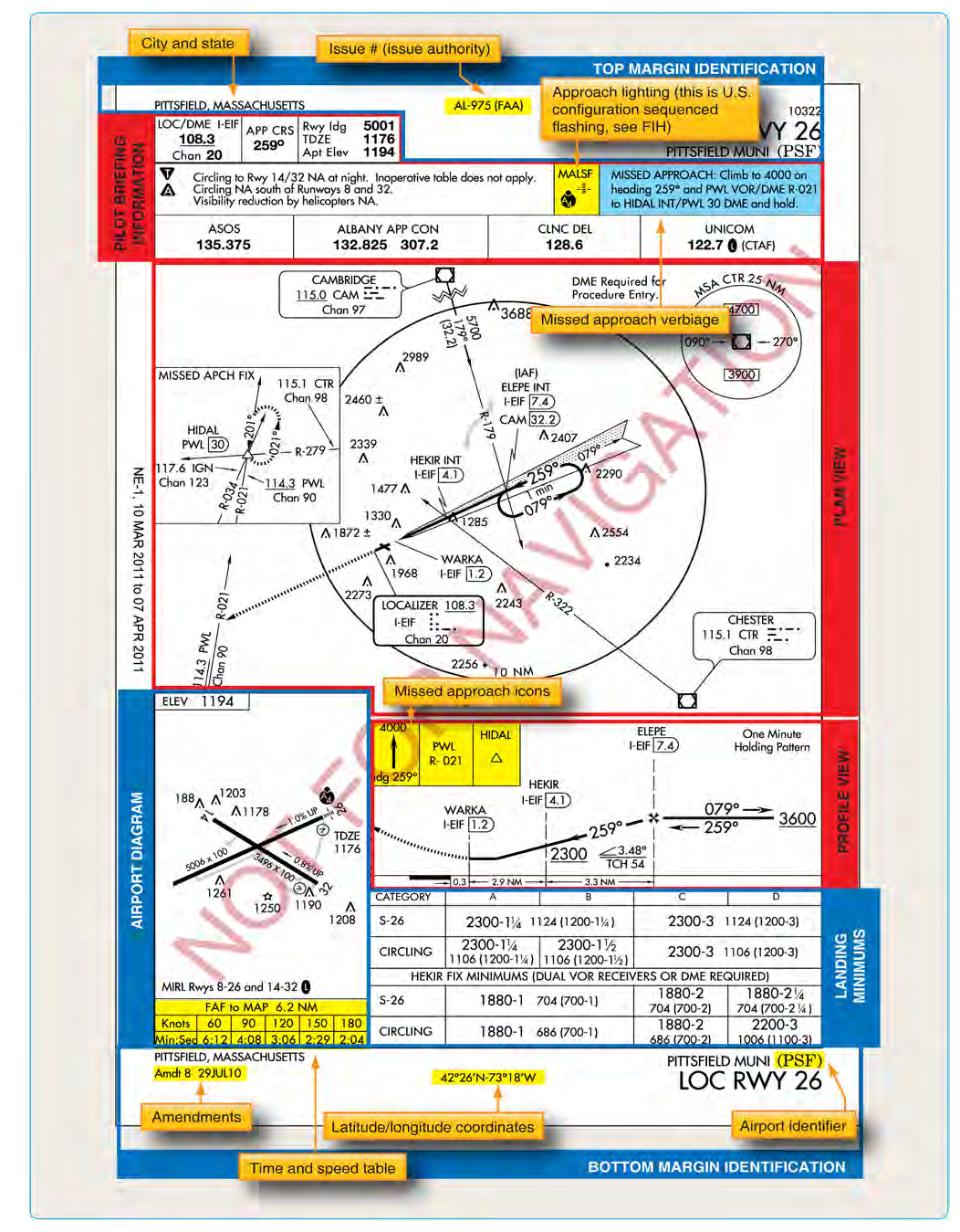
When you unfold an instrument approach procedure (IAP) chart, the largest graphic element you see is the planview — the bird's-eye overhead depiction of the approach environment. Think of it as a top-down map that shows everything you need to know about navigating from the en-route environment down to the point where the runway environment comes into view. The planview is not a simple diagram; it is a precisely coded document that communicates course alignments, distances, altitude constraints, fix types, obstacle information, and airspace boundaries in a compact, standardized format. Mastering its scale, symbology, and fixes is one of the most rewarding skills you will develop as an instrument student — and one of the most heavily tested areas on the FAA Instrument Rating knowledge exam.
IAP charts in the United States are published under FAA specifications and produced primarily by the National Aeronautical Charting Office (NACO), now part of the FAA's Aeronautical Information Services. The format follows standards outlined in the Instrument Procedures Handbook (FAA-H-8083-16) and the Aeronautical Chart User's Guide. Every element on the planview has a specific meaning, and learning to decode each one transforms a confusing jumble of lines and symbols into a clear mental picture of the approach.
Scale and Orientation
One of the first things to understand about the planview is that it is not drawn to a uniform scale. The chart producer uses whatever scale is necessary to show the complete approach procedure, and that scale varies from chart to chart depending on the geographic extent of the procedure. A long RNAV approach with a wide initial segment might use a much smaller scale than a tight VOR approach at a towered airport. The scale is printed on the chart — typically shown as a bar scale in nautical miles — and you should always check it before estimating distances visually.
Orientation is always north-up unless the procedure is so long or geographically awkward that north-up would waste too much space. In those rare cases, the chart will be oriented so the final approach course runs roughly toward the top of the page, and a north-pointing arrow is provided for reference. In practice, you should always verify orientation using the compass rose or north arrow rather than assuming.
The planview typically uses two different levels of detail. The area immediately surrounding the airport and final approach segment is drawn at a larger (more detailed) scale inside what is called the detail area or mileage breakdown box, while the outer portions of the approach — where the initial and intermediate segments live — may be drawn at a smaller scale. This dual-scale approach allows the chart to show both the wide procedural context and the fine-grained detail of the final approach course without requiring an unwieldy sheet of paper.
Key Symbology
Every line, box, and icon on the planview follows a standardized symbology system. Here are the most important elements you will encounter:
- Course lines: Solid lines with arrows show the prescribed track for each segment of the approach. The final approach course is the most prominent, usually drawn as a bold line pointing toward the runway. Feeder routes from en-route fixes are shown with thinner lines.
- Magnetic courses: Numeric course values (e.g., 275°) are printed alongside course lines. These are magnetic courses that you fly on your heading indicator or course deviation indicator (CDI).
- Distance values: Segment lengths in nautical miles are printed along course lines, often inside a small box or circle. These tell you how far you travel between fixes on that segment.
- Minimum Safe Altitude (MSA) circle: A dashed circle centered on a navigation fix (often the airport or a nearby VOR/NDB) showing the minimum altitude that provides 1,000 feet of obstacle clearance within 25 nautical miles of the fix. The MSA is divided into sectors if terrain varies significantly around the airport. The MSA is an emergency reference only — it is not an operational altitude for the approach itself.
- Obstacles: Significant obstacles within the planview area are depicted with a small obstruction symbol (a dot with a spike, or a group-obstruction symbol). The elevation of the obstacle is printed nearby. Obstacles that penetrate the obstacle clearance surface of the approach are highlighted or noted with a bold symbol.
- Holding patterns: If the procedure includes a published holding pattern — for course reversal or delay — it appears on the planview as a racetrack oval with the inbound course and outbound leg depicted. The holding fix is identified, and the direction of turns (standard right turns unless otherwise noted) is shown.
- Procedure turns: A barbed arrow symbol shows a procedure turn (PT) when one is required for course reversal. The procedure turn is always depicted on the side where you perform it, with a notation showing the course and distance limit (e.g., "remain within 10 NM").
- Airspace rings: Class B, C, D, and special-use airspace boundaries that affect the approach environment may be shown as dashed or shaded circles or arcs. These remind you of communication or clearance requirements.
- Navigation facility symbols: VORs appear as the familiar hexagon (compass rose symbol), NDBs as a circle with dots, and RNAV waypoints as four-pointed stars or "fly-over" waypoints as circled four-pointed stars.
Types of Fixes and How to Read Them
Fixes are the backbone of the planview. Each fix marks a specific geographic point where something procedurally significant happens — a course change, an altitude constraint, a timing check, or a transition from one approach segment to the next. The FAA defines four primary approach segments: initial, intermediate, final, and missed approach. Fixes mark the boundaries of these segments.
- Initial Approach Fix (IAF): The starting gate of the approach procedure. Depicted on the planview with the fix name in bold and often accompanied by a speed/altitude note. When ATC clears you for the approach, the IAF is where you begin flying the published procedure. Multiple IAFs may exist for one approach to allow arrival from different directions.
- Intermediate Fix (IF): Marks the beginning of the intermediate segment, where you should be stabilized on the inbound course at the appropriate airspeed and configuration. On RNAV charts this is often labeled "IF" in parentheses below the fix name. On older charts it may not be separately labeled but is implied at the point where the initial and intermediate segments meet.
- Final Approach Fix (FAF): Perhaps the most critical fix on a non-precision approach. Depicted by a Maltese cross symbol (a bold X with flared ends) on the planview and the profile view. This is the point where you begin your final descent to the Minimum Descent Altitude (MDA). On a precision approach (ILS), the FAF is where the glideslope intercept occurs; it is depicted by a lightning-bolt arrow symbol in the profile view rather than the Maltese cross.
- Stepdown Fixes: Some approaches include intermediate fixes between the FAF and the Missed Approach Point (MAP) that allow lower minimum descent altitudes in exchange for confirming you have passed a terrain or obstacle. These appear as named fixes with associated crossing altitudes printed above the course line.
- Missed Approach Point (MAP): The point at which you must execute a missed approach if you have not established the required visual references. On time-based approaches, the MAP is determined by elapsed time from the FAF; on GPS approaches, it is a named waypoint. It is usually the runway threshold or a point over the runway.
- Fly-Over vs. Fly-By Waypoints (RNAV): On GPS/RNAV charts, a standard waypoint (four-pointed star) is a fly-by fix — the FMS begins turning before the fix to anticipate the course change. A circled four-pointed star is a fly-over fix — the aircraft must cross directly over it before turning. Fly-over waypoints are used where early turns would compromise obstacle clearance.
Why It Matters for Safety
Misreading the planview can have serious consequences. Confusing an MSA for an approach altitude, misidentifying the FAF, or overlooking a stepdown fix can all lead to controlled flight into terrain (CFIT). The FAA has identified CFIT as one of the leading causes of fatal accidents in instrument meteorological conditions. A thorough planview brief before every approach — conducted in cruise, not on final — gives you the mental model needed to fly the procedure with confidence and to catch ATC routing errors before they become dangerous.
During your pre-approach briefing, walk through the planview in the order you will fly it: locate the IAF you will use, trace the initial segment course and altitude, identify the intermediate fix and the descent that begins there, find the FAF and its crossing altitude, note any stepdown fixes, and confirm the MAP. Check the MSA for your sector as a backup in case of emergency. Note any nearby obstacles or special-use airspace that might affect your situational awareness.
Key Numbers and Rules
- The MSA circle provides 1,000 feet of obstacle clearance within 25 NM of the reference fix (some facilities use a 30 NM radius — always read the chart).
- A procedure turn must be completed within the distance printed on the chart (commonly 10 NM from the PT fix) and at or below the published PT altitude.
- Fly-over waypoints require crossing the fix before initiating a turn; fly-by waypoints anticipate the turn. Mixing these up on an RNAV approach can result in flying outside obstacle clearance areas.
- All courses on U.S. approach charts are magnetic, not true.
- The Maltese cross symbol on the planview always denotes the FAF on a non-precision approach. Do not confuse it with the stepdown fix symbol.
- Distances between fixes are in nautical miles; time values (when shown) are in minutes and seconds.
Common Test Traps
- Treating the MSA as an approach altitude: The MSA is an emergency reference for obstacle clearance — it is not authorized for flying the approach procedure. The FAA knowledge test often presents the MSA alongside procedural altitudes to see if you distinguish them.
- Assuming uniform scale: Students who estimate distances by eyeballing the planview without checking the bar scale frequently get distances wrong. Always use the printed scale.
- Maltese cross confusion: The Maltese cross marks the FAF on non-precision approaches. On precision approaches, the glideslope intercept serves the equivalent function and the cross is NOT used. Mixing these up is a classic exam error.
- Fly-over vs. fly-by waypoints: Forgetting that a circled waypoint symbol means fly-over (must overfly before turning) rather than fly-by (begin turn early) is a common trap on RNAV-specific questions.
- Procedure turn altitude and distance limits: Students sometimes forget that the procedure turn must be completed within the charted distance limit AND at or below the charted PT altitude — both constraints apply simultaneously.