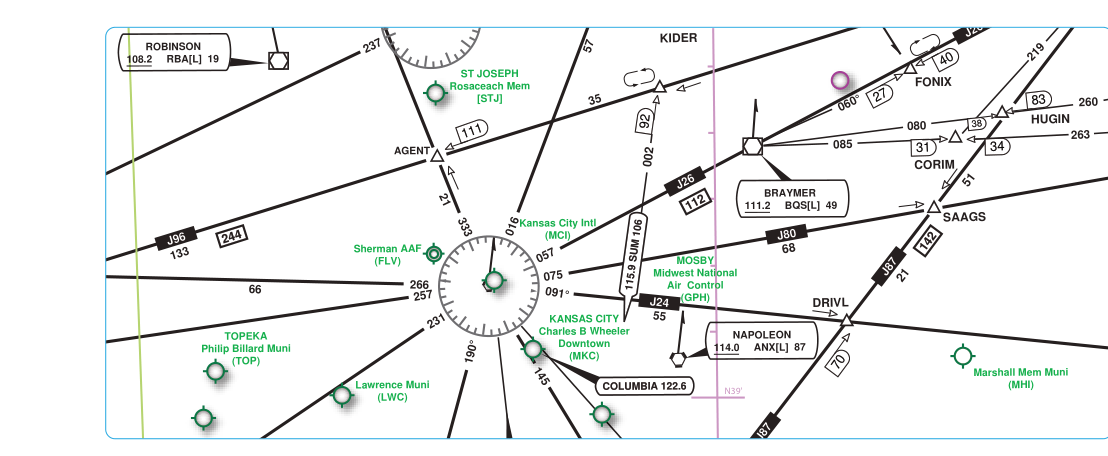
When you climb above 18,000 feet MSL and enter Class A airspace, you enter a different world of navigation. The low-altitude Victor airways that carried you through Class E airspace give way to a separate system of high-altitude routes depicted on IFR Enroute High Altitude charts. These charts — published by the FAA and available through NOAA's Aeronautical Navigation Products — are the essential planning and navigation tool for aircraft operating in the flight levels. Whether you are flying a turbine-powered aircraft on a Jet Route or using a modern GPS-based Q-Route, understanding how these charts work is a core competency for the instrument rating and beyond.
This article breaks down the structure, symbology, and practical use of IFR Enroute High Altitude charts, covering the two primary route types — Jet Routes (J-routes) and Q-Routes — along with the rules, altitudes, and exam traps associated with each.
What IFR Enroute High Altitude Charts Cover
IFR Enroute High Altitude charts depict the airspace structure and navigation routes applicable from 18,000 feet MSL up to and including Flight Level (FL) 450, which is the charted upper limit of the Jet Route and Q-Route structure. Class A airspace itself, as defined under 14 CFR Part 71, actually extends from 18,000 feet MSL up to and including FL 600; FL 450 is simply the ceiling of the charted route structure depicted on these charts, not the top of Class A airspace. Within Class A airspace, all operations must be conducted under Instrument Flight Rules (IFR), regardless of weather conditions. VFR flight is not permitted.
Because all aircraft in Class A airspace are on IFR clearances and under positive ATC control, the chart is optimized for route structure and navigation aids rather than terrain depiction. High Altitude charts are published at a smaller scale than their low-altitude counterparts — typically 1 inch equals about 50 nautical miles — allowing a single set of charts to cover large geographic areas. The continental United States is covered by a set of charts designated H-1 through H-6 (and additional charts for Alaska and the Pacific).
The chart depicts VORs, VOR/DME facilities, and VORTACs that serve as the backbone of Jet Route navigation, along with waypoints and fixes used by Q-Routes. Because the high-altitude environment is dominated by long-range jet aircraft and turboprops, the chart emphasizes airways, ARTCC (Air Route Traffic Control Center) boundaries, and communication frequencies rather than the approach-related information found on low-altitude charts.
Jet Routes: The J-Route System
Jet Routes — commonly called J-routes — are the high-altitude equivalent of the Victor airways found on low-altitude enroute charts. Each Jet Route is identified by the letter J followed by a number (for example, J80 or J146). Like Victor airways, Jet Routes are defined as 8 nautical miles wide — 4 nautical miles on each side of the centerline — and are centered on VOR radials connecting VORTACs or VOR/DME facilities.
Jet Routes extend from 18,000 feet MSL (FL 180) up to and including FL 450, which is the charted upper limit of the Jet Route structure. Because they are defined by VOR radials, aircraft navigating on J-routes traditionally used VOR receivers, though GPS navigation on these routes is now widely approved for aircraft meeting the equipment requirements outlined in the Aeronautical Information Manual (AIM). The magnetic course, distance in nautical miles between fixes, and the identifying VOR or VORTAC are all labeled along each route segment on the chart.
A key operational point: when operating in Class A airspace, pilots must fly at altitudes specified in 14 CFR Part 91's hemispheric rule as modified by ATC clearances and published flight levels. In practice, ATC assigns specific flight levels, and pilots are expected to maintain those altitudes precisely — Class A airspace does not permit the same altitude flexibility available at lower altitudes.
Q-Routes: GPS-Based High-Altitude Airways
Q-Routes are a more modern addition to the high-altitude route structure, introduced to take advantage of the precision and flexibility of Area Navigation (RNAV) and GPS. They are designated by the letter Q followed by a number (for example, Q13 or Q105). Like J-routes, Q-Routes are 8 nautical miles wide and occupy the same altitude band of FL 180 to FL 450.
The critical difference between J-routes and Q-Routes is that Q-Routes do not need to follow VOR radials. Because they are defined by geographic coordinates (latitude/longitude waypoints), Q-Routes can be routed more directly between city pairs, cutting across terrain that VOR infrastructure does not cover efficiently. This results in shorter, more fuel-efficient routes for operators.
To fly a Q-Route, an aircraft must be equipped with a suitable RNAV system — typically GPS meeting TSO-C129 or TSO-C196 standards, or an equivalent approved system. The AIM provides detailed equipment and performance requirements for RNAV route operations. Q-Routes are depicted on IFR Enroute High Altitude charts with their waypoints (shown as five-letter named fixes), distances, and magnetic courses labeled along the route, just like J-routes.
Chart Symbology and Key Features
Reading a High Altitude chart requires familiarity with its specific symbology. Here are the most important elements you will encounter:
- VORTACs and VOR/DMEs: Depicted with the standard compass rose symbol. The facility box lists the name, frequency, Morse code identifier, and channel number. These are the anchor points for J-route navigation.
- Route identifiers: J-route numbers and Q-route numbers are printed in blue along the centerline of each airway, along with the magnetic courses for each direction of flight and the mileage between fixes.
- Compulsory reporting points: Shown as solid triangles. At these fixes, pilots on non-radar contact must report their position to ATC. On modern high-altitude flights with radar coverage, ATC often waives position reports, but pilots must know the requirement.
- Non-compulsory reporting points: Shown as open triangles. Position reports are made at these fixes only when requested by ATC.
- ARTCC boundaries: Depicted as heavy dashed lines. When crossing an ARTCC boundary, pilots will typically be handed off from one Center controller to another.
- Mileage between fixes: Printed as blue numbers along the airway, indicating the nautical miles between adjacent intersections or navaids.
- MEA (Minimum Enroute Altitude): Unlike low-altitude airways, high-altitude routes in Class A airspace generally operate well above terrain, so MEA concerns are less prominent on high-altitude charts — but obstruction clearance altitudes are still established for each route segment.
Why This Matters: Class A Airspace and IFR Operations
Understanding High Altitude charts is not just an academic exercise. Every pilot who intends to operate turbine aircraft or high-performance piston aircraft at the flight levels must be able to file and fly these routes. Because Class A airspace requires an IFR clearance and two-way radio communication with ATC at all times, there is no room for ambiguity about route structure or waypoint identification.
From a safety standpoint, the separation standards in Class A airspace are predicated on all aircraft being on known routes and altitudes. The structured J-route and Q-Route system allows ATC to predict aircraft positions, apply longitudinal and lateral separation, and sequence traffic efficiently at speeds and altitudes where visual separation is impossible. A misread chart or incorrect route entry in the flight management system (FMS) can put an aircraft on a conflicting flight path with another jet traveling at 500 knots.
For the instrument rating practical test and knowledge exam, you are expected to understand the difference between the low-altitude Victor airway system and the high-altitude J-route/Q-Route system, including their altitude applicability, width, and navigation basis.
Key Numbers and Rules
- Charted Jet Route/Q-Route altitude band: FL 180 (18,000 feet MSL) to FL 450, inclusive — the charted high-altitude route structure. Class A airspace itself extends from 18,000 feet MSL up to and including FL 600 (14 CFR §71.33).
- Airway width: Both J-routes and Q-Routes are 8 nautical miles wide (4 NM each side of centerline).
- J-routes: Based on VOR/VORTAC radials; identified by the letter J plus a number.
- Q-Routes: Based on RNAV/GPS; identified by the letter Q plus a number; require a suitable RNAV system.
- Class A airspace rule: All flight must be under IFR; no VFR permitted (14 CFR §91.135).
- Two-way radio and transponder: Required at all times in Class A airspace (Mode C transponder required).
- Chart scale: Approximately 1 inch = 50 NM; coverage from FL 180 to FL 450.
- Continental US coverage: Charts H-1 through H-6 (plus supplemental charts for Alaska and the Pacific).
Common Test Traps
- Confusing J-routes with Victor airways: Victor airways apply from 1,200 feet AGL (or the floor of Class E) up to but not including 18,000 feet MSL. J-routes begin at 18,000 feet MSL. The boundary is FL 180, not FL 175 or FL 185.
- Assuming Q-Routes are VOR-based: Q-Routes are RNAV/GPS routes defined by coordinate-based waypoints, not VOR radials. An aircraft without an approved RNAV system cannot legally fly a Q-Route.
- Misidentifying compulsory vs. non-compulsory reporting points: Solid triangle = compulsory; open triangle = non-compulsory. This is the same convention on both low- and high-altitude charts, but high-altitude exams test it frequently.
- Forgetting that all Class A operations are IFR: There are no weather minimums to evaluate in Class A — VFR is simply not allowed. A student who tries to apply VFR cloud clearance rules above FL 180 has misunderstood the airspace fundamentally.
- Airway width errors: Both J-routes and Q-Routes are 8 NM wide total — some students confuse this with the 4 NM half-width, or incorrectly recall a different width for Q-Routes versus J-routes.
- Confusing the charted route structure ceiling with the top of Class A airspace: FL 450 is the upper limit of the charted Jet Route/Q-Route structure, but Class A airspace extends up to and including FL 600.