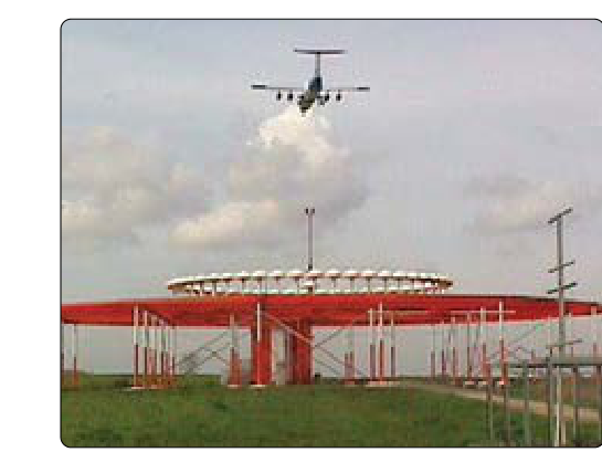
The VHF Omnidirectional Range, universally known as the VOR, has served as the primary ground-based navigation aid for instrument flight in the United States for decades. Even as GPS and RNAV have expanded, the VOR network remains a foundational backup and the legal basis for many published instrument procedures. For the instrument rating candidate, a thorough command of how VOR signals work, what the different station types offer, and how to apply that knowledge in the cockpit is absolutely essential — both on the knowledge test and in actual IFR operations.
This article breaks down the physics of the VOR signal, how your aircraft's receiver decodes that signal into a usable course, the differences among VOR, VOR/DME, and VORTAC stations, and the practical, safety-critical considerations that flow from each.
How the VOR Signal Works
A VOR ground station transmits on a frequency between 108.0 and 117.95 MHz — the VHF (very high frequency) band. Because VHF signals travel in essentially straight lines and do not follow the curvature of the Earth, VOR reception is fundamentally line-of-sight. This is one of the most heavily tested facts about VOR: the usable range of a VOR station depends on the altitude of the aircraft. The higher you fly, the farther you can receive a usable signal.
The station simultaneously broadcasts two signals that together encode azimuth (bearing) information:
- Reference phase signal: An omnidirectional signal broadcast equally in all directions. This signal serves as the phase reference and does not change with bearing.
- Variable phase signal: A directional signal that rotates at 30 revolutions per second. The phase of this rotating signal changes depending on the bearing from the station at which an aircraft receives it.
Your aircraft's VOR receiver compares the phase difference between these two signals. At magnetic north (360°) from the station, the two signals are exactly in phase. As you move clockwise around the station, the variable signal's phase shifts proportionally. At 090° the variable is 90° behind the reference; at 180° it is 180° out of phase; and so on. The receiver converts this phase difference into a radial indication on your course deviation indicator (CDI) or HSI. This is why VOR bearings are called radials: they radiate outward from the station and are always expressed as magnetic bearings from the station.
Reading the CDI: FROM vs. TO and Course Selection
A VOR receiver doesn't just measure the phase difference; it also determines whether the aircraft is flying toward or away from the station on the selected course. The TO/FROM indicator (sometimes called the ambiguity indicator) tells you which of these conditions applies. Select an Omni Bearing Selector (OBS) setting equal to your approximate magnetic bearing to the station, and the flag should read TO; set it to the approximate bearing from the station and the flag reads FROM. When the selected course is roughly perpendicular to the actual radial, the indicator may show OFF, meaning the signal is too ambiguous to resolve TO or FROM.
The full-scale deflection of a standard CDI needle on a VOR is 10° of angular error on each side of the selected course — five dots at 2° per dot on most instruments. This angular nature of VOR guidance is critical: the actual width of a course corridor in nautical miles grows the farther you are from the station. Close to a VOR the full-scale deflection might represent only a mile or two of lateral deviation; 50 nm away it represents much more. This is why VOR approaches are flown with the station close ahead and why positional awareness remains essential on airways far from any VOR.
VOR Station Types
Standard VOR
A plain VOR station provides azimuth information only. It operates in the 108–117.95 MHz band and broadcasts voice identification (typically a three-letter Morse code identifier repeated every 30 seconds or so), as well as an optional voice ATIS or weather broadcast on some stations. If the identifier is being broadcast, the station is operational; if you hear only voice or silence without the identifier tone, treat the station as unreliable.
VOR/DME
A VOR/DME is a VOR station co-located with a Distance Measuring Equipment (DME) transponder. DME operates in the UHF band (962–1213 MHz) and works by having the aircraft's DME interrogator send a pair of pulses to the ground station; the ground station replies after a fixed delay; and the avionics measure the round-trip time to calculate slant-range distance in nautical miles. Because this is slant range — not direct over-ground distance — there is a small error that becomes negligible beyond a few miles or at typical en route altitudes. DME readout is displayed in nautical miles, and many units also display groundspeed and time-to-station when tracking directly to or from the facility.
The pairing of VOR azimuth and DME distance gives a pilot a rho-theta fix — a precise position from a single station without needing a second VOR cross-radial. This makes VOR/DME stations especially valuable for instrument approaches and for holding patterns where DME arc procedures may be published.
VORTAC
A VORTAC is the co-location of a VOR and a TACAN (Tactical Air Navigation) station operated by the military. TACAN itself provides both bearing and distance information, but military bearing encoding is different from the VOR system. When the two are co-located, civilian aircraft receive VOR azimuth from the VOR component and distance from the TACAN's DME component — which is fully compatible with civilian DME equipment. Military aircraft can use both the bearing and distance functions of the TACAN directly. The practical result for a civilian IFR pilot: a VORTAC gives you exactly the same azimuth plus DME capability as a VOR/DME, and the two are operationally indistinguishable from the cockpit. VORTAC stations are the most common type in the continental United States.
Service Volumes and Altitude Limitations
The FAA defines Standard Service Volumes (SSVs) for VOR stations, establishing the altitude and distance ranges within which the signal is guaranteed to meet accuracy and identification standards. The three original SSV classes are:
- Terminal (T): Usable to 25 nautical miles, between 1,000 and 12,000 feet AGL. These stations support instrument approaches and are often found at or near airports.
- Low Altitude (L): Usable to 40 nautical miles, between 1,000 and 18,000 feet MSL. These support low-altitude airways (Victor airways) up to but not including FL180.
- High Altitude (H): Usable to 40 nautical miles between 1,000 and 14,500 feet AGL, expanding to 100 nautical miles from 14,500 feet to 18,000 feet, 130 nautical miles from 18,000 feet to 45,000 feet, and 100 nautical miles from 45,000 feet to 60,000 feet. These support Jet routes and high-altitude IFR operations.
The FAA has also introduced an expanded SSV classification called VOR Federal Airway (VFA) as part of modernization efforts, with increased service volumes for certain stations retained under the VOR Minimum Operational Network (MON) program. The MON is the FAA's plan to maintain a reduced but strategically placed set of VORs as a GPS backup, ensuring that a pilot can always navigate to an airport with a VOR-based approach even during a GPS outage.
Why VOR Principles Matter for IFR Pilots
Understanding the underlying signal principles — not just how to twist the OBS — directly affects safety and decision-making in several ways. First, recognizing that VOR accuracy degrades with distance and low altitude helps you assess when a cross-radial fix is reliable enough for navigation or when you need DME confirmation. Second, knowing that VOR is susceptible to scalloping (signal bending caused by terrain reflections) and propeller modulation (a buzzing noise on the audio from certain propeller RPM settings) teaches you to cross-check instruments rather than trust a single source. Third, understanding the VORTAC's TACAN component explains why VORTAC stations are so common near military airspace and why DME is always available there.
Instrument procedures — holding patterns, DME arcs, VOR approaches, and airways — are all designed around the specific signal characteristics and service volumes of these station types. A pilot who understands the underlying principles can adapt when a station is out of service, when a NOTAM restricts DME, or when a low-altitude flight makes VOR reception marginal.
Key Numbers and Rules
- VOR frequency band: 108.0 – 117.95 MHz (VHF)
- DME frequency band: 962 – 1213 MHz (UHF)
- CDI full-scale deflection: ±10° (typically 5 dots at 2° each)
- Morse code identifier: Broadcast approximately every 30 seconds; absence means the station is unreliable
- Terminal SSV: 25 nm, 1,000–12,000 ft AGL
- Low Altitude SSV: 40 nm, 1,000–18,000 ft MSL
- High Altitude SSV: 40 nm (1,000–14,500 ft AGL), 100 nm (14,500–18,000 ft), 130 nm (18,000–45,000 ft), 100 nm (45,000–60,000 ft)
- VORTAC = VOR azimuth + TACAN DME (civilian use: functionally same as VOR/DME)
- Radials are FROM the station, expressed in magnetic degrees
Memory Aid
"The radial RADIATES out" — Radials always radiate outward from the station and are named from the station's perspective. When you are northeast of a VOR, you are on the 045° radial. Your course TO the station on that radial is 225° (the reciprocal). Keeping radial direction straight is one of the most common stumbling blocks for VOR students; anchoring the idea that radials go from the station outward eliminates the confusion.
Common Test Traps
- Radial vs. bearing confusion: The FAA loves to ask what radial an aircraft is on versus what heading to fly. Remember: radials are FROM the station. If ATC says "fly the 270° radial FROM the VOR," you are going west of the station and flying east (090°) takes you to it.
- TO/FROM flag reversal: Flying into a station on a selected course will show TO; passing the station, the flag flips to FROM. A common trap question sets up a scenario where a student mistakes a FROM indication for course reversal.
- CDI sensitivity and distance: Full-scale deflection is always 10° regardless of distance, but the actual lateral distance that 10° represents grows with distance from the station — a fact tested in practical judgment questions.
- VORTAC vs. VOR/DME operational differences: There are none for civilian pilots. Test questions sometimes imply a distinction in usability; in practice both provide the same VOR azimuth plus civilian DME distance.
- Service volume limits: Using a Terminal VOR for en route navigation beyond 25 nm or below the stated altitude floor is outside its standard service volume; the signal may be unreliable, and the FAA will test whether you know these boundaries.