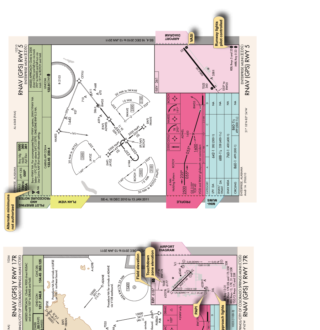
Every instrument approach procedure (IAP) chart is a carefully engineered document that communicates dozens of critical pieces of information through a standardized visual language. Whether you are flying an ILS approach to minimums in low IMC or executing an RNAV (GPS) approach to a remote airfield, the chart symbology tells you exactly where to go, how fast to descend, and how low you can safely fly before you must see the runway environment. The FAA and the National Aeronautical Charting Office (NACO) use a consistent format across all approach charts — but RNAV and ILS approaches each have unique symbols you must learn to read instantly in the cockpit.
This article walks through the major sections of an IAP chart, highlights the symbology specific to ILS and RNAV (GPS/RNP) approaches, explains what each symbol means operationally, and covers the most commonly tested knowledge-test traps. By the end, you should be able to open any approach chart and decode it with confidence.
How IAP Charts Are Organized
Standard U.S. government approach charts (published by the FAA Aeronautical Information Services) follow a consistent layout with five main sections: the margin identification (top and bottom strips), the briefing strip, the plan view, the profile view, and the minimums section. Understanding where each type of symbology lives in this structure is the first step to reading charts quickly.
Margin Identification
The top margin contains the approach name, airport name, city, state, and chart index number. The approach name itself carries critical information: ILS OR LOC RWY 28L tells you the primary navaid type, a backup type, and the landing runway. An approach named RNAV (GPS) RWY 10 indicates a GPS-based approach with performance-based navigation. If you see RNAV (RNP) RWY 24, that chart requires Authorization Required (AR) RNP capability — a higher standard not available in all aircraft.
ILS-Specific Symbology
The ILS (Instrument Landing System) approach provides both lateral guidance via the localizer and vertical guidance via the glide slope. These two elements are represented distinctly throughout the chart.
In the plan view, the localizer course is shown as a bold feathered line extending outbound from the runway threshold. The feathered or dashed portion indicates the back course, while the solid line represents the front course. The localizer antenna symbol — a small chevron-like icon — appears near the departure end of the runway on the chart. The glide slope intercept altitude is annotated at the point where the glide slope normally intercepts the final approach course (typically at the final approach fix, or FAF). On an ILS, the FAF is identified by the lightning-bolt symbol (⊗), which specifically means the FAF is defined by glide slope intercept rather than a GPS or DME fix.
In the profile view, the glide slope is drawn as a descending line with the glide slope angle prominently labeled (e.g., GS 3.00°). The decision altitude (DA) rather than a minimum descent altitude (MDA) is published for ILS approaches because the glide slope provides continuous vertical guidance. The DA is the height above touchdown (HAT) at which the pilot must initiate a missed approach if the runway environment is not in sight. On the chart you will see the DA expressed both as MSL and HAT, for example DA 1,340 / HAT 200.
The inner marker (IM), middle marker (MM), and outer marker (OM) are depicted as small ellipses along the approach path in the profile view. Because marker beacons are increasingly decommissioned, many current ILS approaches replace the OM with a compass locator (LOM) — depicted as a small circle with a dot — or a named GPS fix serving the same function. DME fixes may substitute as well, shown as a flag-shaped symbol with a distance value.
RNAV-Specific Symbology
RNAV approaches introduce symbology tied to waypoints, required navigation performance (RNP), and vertical navigation (VNAV). Grasping these symbols is essential for modern glass-cockpit IFR flying.
Waypoint Symbols
RNAV waypoints appear as fly-over waypoints (depicted as a four-pointed star inside a circle) or fly-by waypoints (depicted as a plain four-pointed star without the surrounding circle). A fly-by waypoint allows the FMS to begin turning before the fix to roll out on the next course — this is the standard. A fly-over waypoint requires the aircraft to cross directly over the fix before turning, which is used at missed approach points and certain procedurally critical fixes. Confusing these two can result in cutting corners on an approach and flying outside protected airspace.
LNAV, LNAV/VNAV, LPV, and LP Lines
One of the most tested areas of RNAV chart symbology is the minimums section, which can list up to four separate lines of minimums depending on aircraft and avionics capability:
- LPV (Localizer Performance with Vertical guidance): Uses WAAS augmentation to provide lateral and vertical guidance. Accuracy is comparable to an ILS. Minimums use a DA and can go as low as 200 feet HAT, identical to a CAT I ILS in many cases. The glidepath angle is labeled (e.g., GP 3.00°) to distinguish it from an ILS glide slope.
- LNAV/VNAV (Lateral Navigation / Vertical Navigation): Provides advisory vertical guidance using WAAS or baro-VNAV. Uses a DA. Minimums are typically higher than LPV due to wider obstacle clearance requirements for baro-VNAV.
- LNAV (Lateral Navigation only): GPS lateral guidance only; no vertical guidance from the procedure. Uses an MDA rather than a DA. The pilot must level off at the MDA and look for the runway environment.
- LP (Localizer Performance): A WAAS-based lateral-only approach, similar in concept to LNAV but with tighter lateral tolerances, available on some approaches where vertical guidance is not provided. Uses an MDA.
In the profile view of an RNAV approach, the final approach fix (FAF) is shown as a Maltese cross symbol (✛) when it is a named fix. The missed approach point (MAP) is shown as a circle with an enclosing symbol or a bold waypoint label at the runway threshold. For approaches with vertical guidance (LPV, LNAV/VNAV), the DA is reached along the glidepath before the threshold, similar to an ILS.
RNAV Step-Down Fixes and Altitude Annotations
On LNAV-only approaches, step-down fixes between the FAF and MAP may be required before descending to the MDA. These appear as additional altitude restrictions annotated above a small fix symbol in the profile view. Pilots must cross each step-down fix at or above the published altitude. Ignoring a step-down fix is a common cause of controlled flight toward terrain (CFIT) on non-precision approaches.
Why It Matters: Safety and Legal Compliance
Misreading an approach chart symbol is not just a knowledge-test problem — it is a safety hazard. Descending below an MDA when only LNAV guidance is available, or treating an LNAV minimum as a DA and continuing through it without visual contact, can result in CFIT. Using an LPV minimum when your GPS is not WAAS-capable violates 14 CFR Part 91 equipment requirements. The FAA Instrument Flying Handbook and the Instrument Procedures Handbook both emphasize that chart literacy is a foundational IFR skill, not an afterthought.
Key Numbers and Rules
- ILS glide slope typically set at 3°, providing approximately 300 feet of altitude loss per nautical mile.
- Standard ILS CAT I DA: 200 feet HAT with ½ SM visibility (or 1,800 RVR).
- LPV approaches can publish DAs as low as 200 feet HAT when obstacle environment allows.
- LNAV/VNAV minimums are typically 250–350 feet HAT or higher.
- LNAV-only minimums commonly range from 300–500+ feet HAT depending on obstacles.
- RNP AR approaches require specific aircraft and crew authorization; not available on a standard IFR rating without additional qualification.
- The visual descent point (VDP), marked with a 'V' in the profile view, is the recommended point on a non-precision approach from which a normal descent from MDA can be made to the touchdown zone. It is not a mandatory fix but a safety aid.
- Threshold crossing height (TCH) for ILS is typically 50–55 feet AGL, annotated in the profile view.
Memory Aid: DOLLAR (minimums hierarchy)
When reading RNAV minimums from best to most conservative, remember D-O-L-L: DA with LPV (best, most precise), DA with LNAV/VNAV (advisory vertical), LNAV MDA (lateral only), LP MDA (WAAS lateral, tighter than LNAV). Each step down the list means higher minimums and less precision.
Common Test Traps
- DA vs. MDA confusion: ILS and approaches with vertical guidance (LPV, LNAV/VNAV) use a DA — you initiate missed approach at that altitude, not below it. LNAV and LP use an MDA — you may not descend below the MDA, but you can fly level at it until the MAP.
- Fly-over vs. fly-by waypoints: The FAA tests whether you know that a fly-over waypoint (star in a circle) must be crossed before turning. Cutting a fly-over waypoint is a procedural error.
- GS vs. GP: The abbreviation GS refers to an ILS glide slope (radio beam); GP refers to an RNAV glidepath (computed by WAAS). They look similar on the chart but come from different systems.
- Step-down fixes on LNAV approaches: Students often miss that a step-down fix must be crossed at or above its altitude before descending further. Descending past it early is a violation and a safety hazard.
- Using LPV minimums without WAAS: If your GPS receiver is not WAAS-certified (TSO-C145/C146), you cannot use LPV or LNAV/VNAV minimums. You must use LNAV minimums only. The chart does not warn you — the pilot must know the equipment.