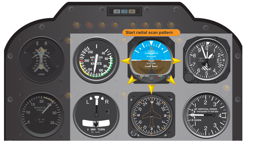
One of the most demanding skills an instrument-rated pilot must develop is the ability to gather accurate information from the cockpit instrument panel quickly and continuously. Unlike visual flight, where the horizon provides an instant reference, IFR flight requires the pilot to mentally construct a picture of the aircraft's attitude from multiple gauges—each telling only part of the story. The method you use to move your eyes across those gauges is called your instrument scan, and doing it well is the difference between smooth, precise flight and the kind of excursions that lead to accidents. Two FAA-recognized scan techniques form the foundation of attitude instrument flying: the radial scan and the selective radial scan.
Understanding both techniques—not just their mechanics, but the reasoning behind them—will help you pass your instrument knowledge test and, more importantly, fly accurate approaches and holds in real IMC. Let's build that understanding from the ground up.
The Role of the Attitude Indicator as the Master Reference
Before examining scan patterns, it's essential to understand why the attitude indicator (AI) sits at the center of every FAA-approved scan technique. The Instrument Flying Handbook (FAA-H-8083-15) classifies flight instruments into three functional categories: control instruments (those that give direct attitude and power information), performance instruments (those that show the result of your control inputs), and navigation instruments. The AI is the primary control instrument. It shows pitch and bank simultaneously and responds instantly to control input, with no lag caused by aircraft inertia. Every scan technique begins and returns to the AI because it provides the earliest, most direct indication of what the airplane is doing.
The supporting performance instruments—altimeter, airspeed indicator, vertical speed indicator (VSI), turn coordinator, and heading indicator—confirm whether the attitude you're holding is producing the desired result. Think of the AI as your hypothesis and the performance instruments as the evidence that tests it. If your AI shows wings level with a 2° nose-up pitch and your altimeter is unwinding, something is wrong—you need to re-examine both.
The Radial Scan: Systematic Coverage of the Entire Panel
The radial scan—sometimes called the hub-and-spoke scan—is the foundational technique described in the Instrument Flying Handbook. Picture the AI as the hub of a wheel. From the hub, your eyes travel outward along a spoke to a supporting instrument, pause long enough to read that instrument accurately, then return to the hub before moving along the next spoke to the next instrument. You systematically work your way around the panel in this fashion: AI → altimeter → AI → heading indicator → AI → airspeed → AI → VSI → AI → turn coordinator → AI, and so on, always snapping back to the AI between each stop.
The key discipline of a radial scan is the return to center. Every excursion away from the AI ends with the eyes back on the AI. This prevents the most common beginner error—becoming fixated on a single instrument—and ensures the AI never goes unmonitored for more than a fraction of a second. It also provides a natural rhythm that helps pilots avoid the tendency to rush the scan when workload spikes.
Reading Instruments Properly During the Scan
The scan is only useful if each instrument glance actually extracts meaningful information. For most instruments, a proper glance takes roughly one to two seconds—long enough to read the actual value, not just note the needle position. The altimeter, for instance, requires reading all three hands (or a digital readout) to determine altitude to within 100 feet. The VSI, by contrast, is best read as a trend (climbing, descending, level) rather than an exact rate because of its inherent lag. Training yourself to read each instrument at the right level of detail—without dwelling too long—is part of what makes an efficient scan.
The Selective Radial Scan: Adapting to Phase of Flight
As pilots gain experience, they learn that not all instruments carry equal importance at all times. During a stabilized cruise segment, the altimeter, heading indicator, and airspeed indicator are the most critical performance instruments. During an ILS approach, the CDI, glideslope indicator, and altimeter demand more frequent attention. During a turn, the turn coordinator and heading indicator need closer monitoring. The selective radial scan adapts the basic hub-and-spoke model by deliberately giving more attention—more frequent returns—to the instruments most relevant to the current task.
The AI remains the hub. What changes is the distribution of spokes. If you are flying a precision approach in IMC, your scan naturally elongates toward the CDI/glideslope and the altimeter. If you are holding altitude in cruise, the altimeter and VSI receive extra visits. The selective radial scan is not random; it is purposeful prioritization built on top of the systematic radial foundation. The Instrument Flying Handbook describes this prioritization as being driven by the primary and supporting instrument concept: for any given flight phase and parameter (pitch, bank, power), one instrument is designated the primary source of information, and the selective scan weights visits to primary instruments most heavily.
Primary and Supporting Instruments by Phase
A few important examples help make this concrete:
- Straight-and-level cruise (pitch): The altimeter is the primary pitch instrument (it shows whether the desired altitude is being held), while the AI and VSI are supporting.
- Straight-and-level cruise (bank): The heading indicator is primary (it shows whether heading is being maintained), while the AI and turn coordinator are supporting.
- Standard-rate turn: The turn coordinator becomes primary for bank; the AI and heading indicator are supporting.
- Constant airspeed climb: The airspeed indicator is primary for pitch; the altimeter becomes primary once level-off begins.
Recognizing these priorities allows the selective radial scan to channel attention efficiently without abandoning the AI hub for dangerously long intervals.
Why Scan Technique Matters: Safety and Precision
The consequences of a poor instrument scan appear in accident records with unfortunate regularity. Spatial disorientation—where the vestibular system provides false attitude sensations—is a leading cause of fatal IMC accidents. The only reliable defense is a disciplined, continuous instrument scan that overrides sensory illusions with objective data. When the inner ear tells you you're in a gentle bank but the AI shows 30° of bank, trust the instruments. This is only possible if you are actually looking at the instruments in a pattern that captures changes early.
Beyond safety, scan quality directly determines flight precision. Instrument approaches require maintaining altitude, heading, and airspeed within tight tolerances simultaneously, and those tolerances vary by task. A wandering or fixated scan means one of those parameters is going unmonitored—often the one that first diverges from the desired value.
Common Scan Errors to Understand and Avoid
The Instrument Flying Handbook identifies several classic scan errors that every instrument student struggles with initially:
- Fixation: Staring at one instrument—typically the altimeter or CDI—while the AI, heading, or airspeed drifts unnoticed. Often triggered by an instrument not showing the desired value.
- Omission: Leaving one or more instruments out of the scan entirely. The VSI and turn coordinator are frequent victims, especially during high-workload phases.
- Emphasis: Spending so much time on non-critical instruments (or on the AI itself to the exclusion of performance instruments) that the scan loses balance.
- Chasing the needles: Over-correcting based on rapid, anxious glances before instruments have stabilized, creating pilot-induced oscillations in altitude and heading.
- Scan interruption: Allowing cockpit tasks—radio calls, checklist use, GPS programming—to pause the scan for too long. Good technique involves briefing and pre-loading as much task work as possible during low-workload phases.
Key Numbers and Rules
- The attitude indicator is the hub of both radial scan techniques—eyes always return here first.
- Each instrument glance should last approximately one to two seconds—enough to extract accurate data, not so long as to become fixation.
- In a selective radial scan, the primary instrument for any parameter is the one that most directly shows whether the desired value is being maintained.
- The Instrument Rating ACS (Airman Certification Standards) sets task-specific tolerances rather than one blanket standard—common examples include altitude ±100 feet (or +100/-0 feet at MDA on nonprecision approaches), heading ±10°, and airspeed ±10 knots for many maneuvers—standards only achievable with a disciplined scan.
- Spatial disorientation illusions (leans, graveyard spiral, somatogravic illusion) can override vestibular sense within seconds of entering IMC without visual reference—making a continuous scan a physiological necessity, not just a technique preference.
Memory Aid: Control, Performance, Navigation
C-P-N captures the three instrument categories the FAA uses to organize your scan priorities. C = Control instruments (AI, manifold pressure/RPM) — tells you what the aircraft is doing right now. P = Performance instruments (altimeter, ASI, VSI, heading indicator, turn coordinator) — tells you the result of your control inputs. N = Navigation instruments (VOR, ILS, GPS, ADF) — tells you where you are relative to your route. A healthy scan visits all three categories in proportion to the demands of the current flight phase.
Common Test Traps
- Confusing primary and supporting instruments: On a knowledge test question asking which instrument is primary for pitch during straight-and-level flight, the answer is the altimeter—not the AI. The AI is a control instrument, not a performance instrument in this context.
- Assuming the scan is fixed: The radial and selective radial scans are not the same technique. The selective radial scan adjusts emphasis based on flight phase; test questions may probe whether you understand this distinction.
- Overlooking the VSI lag: The VSI lags actual vertical speed by several seconds. Test questions and practical scenarios exploit this—don't make pitch corrections based solely on a VSI that hasn't settled.
- Thinking fixation only happens to beginners: The FAA emphasizes that even experienced pilots can develop fixation under high workload (e.g., during a missed approach or instrument malfunction). Exam scenarios will present high-workload situations and ask what the correct scan response is.
- Misidentifying the hub instrument: Some students mix up the AI and the heading indicator as the center of the scan. The AI is always hub—it provides simultaneous pitch and bank data that no other instrument duplicates in real time.