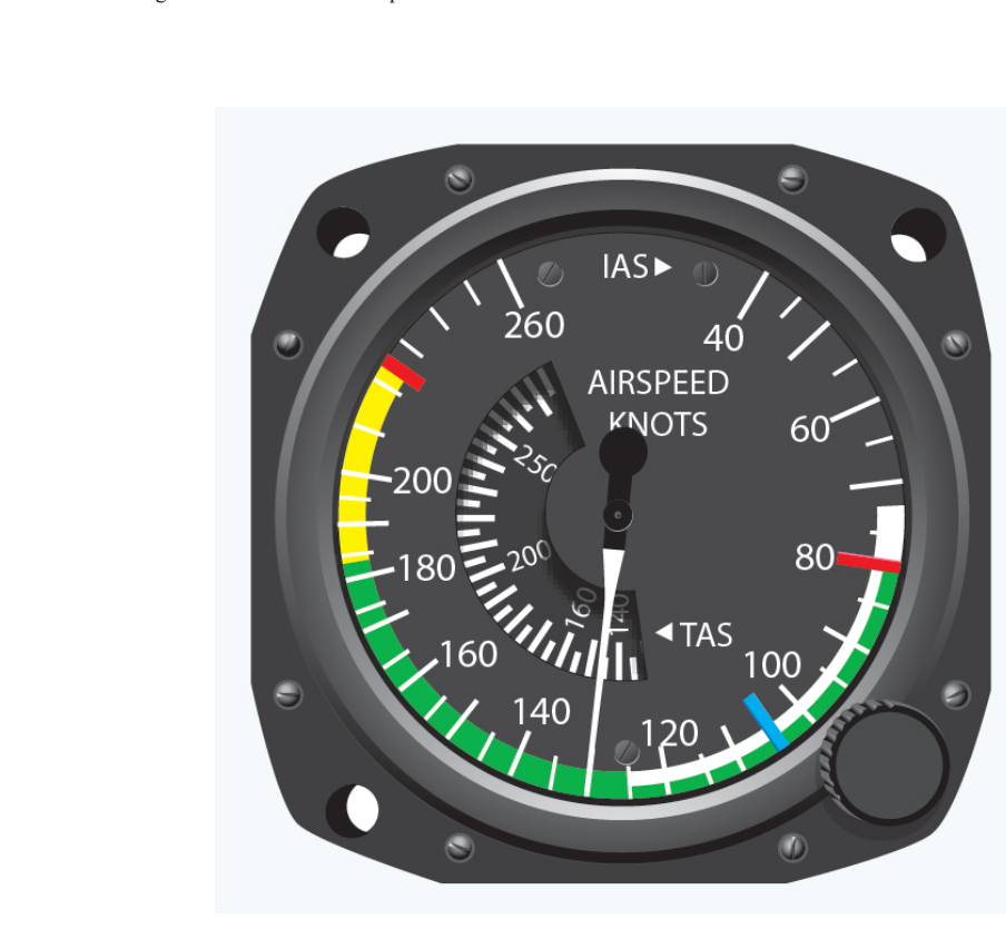
When you transition from VFR flying into the instrument environment, the airspeed indicator (ASI) becomes far more than a cruise-speed reference. During an IFR approach in turbulence, a holding pattern at minimum fuel, or a missed approach with full flaps still extended, every color arc and every V-speed on that dial carries a direct safety consequence. The FAA requires specific airspeed limits to be marked on the ASI of certificated aircraft, and those markings correspond to the same V-speeds that appear in your Pilot's Operating Handbook (POH), your instrument approach procedures, and your practical test standards. Mastering them is non-negotiable for the instrument rating.
This article walks through each ASI marking in detail, explains the aerodynamic and structural reasoning behind each V-speed, and highlights the IFR-specific considerations that trip up instrument candidates on both the knowledge test and the checkride.
How the Airspeed Indicator Works
The ASI measures the difference between ram (pitot) pressure and static pressure. Ram air enters the pitot tube; static air enters the static port. A diaphragm inside the instrument expands and contracts as the pressure differential changes, and that mechanical movement drives the airspeed needle. Because the instrument compares these two pressures, it displays indicated airspeed (IAS) — the raw cockpit reading before any corrections.
In IFR operations you will frequently hear references to calibrated airspeed (CAS), true airspeed (TAS), and Mach number. All ASI color arcs and V-speed limits, however, are expressed in indicated airspeed as shown in the cockpit. That is intentional: the structural and aerodynamic limits the manufacturer determined during certification testing are tied to IAS values regardless of altitude or temperature. As long as you respect the indicated limits, you respect the structural envelope — even though your TAS may be significantly higher at altitude.
The Color-Coded Arcs and Their Meanings
The FAA mandates specific color markings on airspeed indicators for certificated aircraft. Each arc or line marks a critical operational boundary:
- White arc — flap operating range. The white arc runs from VS0 (stall speed in the landing configuration, full flaps, power off) at the lower end to VFE (maximum flap extended speed) at the upper end. Any time you are within the white arc with flaps deployed, you are within the tested, approved range. Flying above VFE with flaps extended can overstress or damage the flap structure.
- Green arc — normal operating range. The green arc runs from VS1 (stall speed in a specified clean configuration, flaps up, power off) at the lower end to VNO (maximum structural cruising speed) at the upper end. You should conduct essentially all normal IFR cruise flight within the green arc. The green arc is the everyday speed band: safe for all normal maneuvers and encounters with light turbulence.
- Yellow arc — caution range. The yellow arc extends from VNO to VNE (never-exceed speed). Flight in the yellow arc is permitted only in smooth air. If you encounter turbulence while in the yellow arc, you risk exceeding structural load limits. On an IFR flight in IMC — where turbulence can appear without visual warning — operating in the yellow arc is a genuine hazard. The practical rule: get back into the green arc before entering clouds.
- Red line — VNE (never-exceed speed). This single red radial line marks the absolute upper airspeed limit. Exceeding VNE can cause flutter, structural failure, or loss of control. It is not a guideline; it is a hard limit. A separate red radial line marking is also used on multi-engine aircraft ASIs for VMC (minimum control speed, air), but this is a distinct and independent marking from VNE, not a shared or reused marking, discussed further in multi-engine contexts.
Critical V-Speeds for IFR Operations
Beyond the color arcs, several V-speeds appear throughout IFR procedures and emergency scenarios. Knowing each definition, its associated marking (if any), and why it matters in IMC is essential:
VA — Maneuvering Speed
VA is the maximum speed at which full, abrupt single-control deflection will not overstress the airframe. At or below VA, if you apply full elevator (or aileron or rudder) deflection, the wing will stall before structural damage occurs. VA is not marked on the ASI — it appears only in the POH. Critically, VA decreases as aircraft weight decreases: a lighter aircraft at the same indicated airspeed generates less lift margin before the load limit is reached, so the published VA applies only at or near maximum gross weight. In turbulence or when ATC assigns holding, instrument pilots routinely slow to VA or the published turbulence penetration speed. Never apply full simultaneous multiple-control inputs even at VA, because combined deflections can still overstress the structure.
VFE — Maximum Flap Extended Speed
VFE is the upper limit of the white arc. During an IFR approach, you often extend flaps incrementally. If you are flying the localizer at an airspeed above VFE and extend flaps, you can bend or tear the flap hinges. Always confirm you are at or below VFE before selecting a flap setting. On a precision approach glideslope, monitor airspeed diligently: the temptation to chase altitude with power without reducing speed can push you above VFE.
VNO — Maximum Structural Cruising Speed
VNO is the top of the green arc. You may exceed VNO only in smooth air, and even then you must not exceed VNE. In IFR cruise at higher altitudes, where TAS climbs well above IAS, pilots sometimes become complacent watching the IAS and assume they have margin. Remember: the arc limits apply to IAS directly — stay in the green in IMC.
VS0 and VS1 — Stall Speeds
VS0 is stall speed in the landing configuration (full flaps, gear down if applicable, power off). It is the bottom of the white arc. VS1 is stall speed in a clean (flaps-up) configuration and forms the bottom of the green arc. Both are 1-G, power-off, coordinated-flight values. In IFR, these speeds matter most on final approach and during a missed approach: adding power abruptly while at VS0-plus-a-few-knots and retracting flaps too quickly can raise your stall speed toward the higher, clean-configuration VS1 before you have accelerated sufficiently, reducing your stall margin.
VNE — Never-Exceed Speed
The red line. In a rare IFR scenario — an inadvertent spiral dive in IMC — airspeed can build rapidly. Recovery from an unusual attitude must include immediate power reduction and leveling the wings using coordinated aileron and rudder, followed by a smooth (not abrupt) return to level flight, precisely because pulling back abruptly at high speed risks exceeding VNE and can cause structural failure or accelerated-stall-induced secondary spiral.
Why These Markings Matter Specifically in IFR
In VMC, a pilot can see turbulence in the form of cumulonimbus clouds or mountain wave lenticulars and avoid them. In IMC, turbulence arrives without visual warning. The yellow arc becomes actively dangerous because a sudden gust can add a large load factor spike before you have time to react. The instrument pilot's conservative rule is: plan cruise speed within the green arc during any IMC flight where turbulence is possible — which, practically, is almost always.
IFR approach procedures sometimes publish recommended approach speeds. These speeds are chosen to provide adequate stall margin while keeping you within the white arc for flap extension. Flying a stabilized approach at the correct airspeed — neither too fast (risk of VFE exceedance or long landing) nor too slow (stall margin reduction) — requires internalizing these limits before you ever start the approach briefing.
Key Numbers and Rules
- White arc: VS0 (bottom) to VFE (top) — flap operating range.
- Green arc: VS1 (bottom) to VNO (top) — normal operations; all approved maneuvers.
- Yellow arc: VNO to VNE — smooth air only; avoid in IMC.
- Red radial line: VNE — never exceed under any circumstances.
- VA is not on the ASI; it is in the POH and decreases with lighter weight.
- All arc and V-speed limits are expressed in indicated airspeed, not TAS or CAS.
- Exceeding VFE with flaps deployed risks structural flap damage.
- In turbulence, slow to VA or the manufacturer's recommended turbulence penetration speed.
Memory Aid
For the arcs in sequence from slow to fast, remember: "White, Green, Yellow, Red" — think of it as a traffic-light extended analogy. White is the special slow-speed flap zone; Green means go ahead and cruise normally; Yellow means caution — smooth air only; Red means stop — never exceed. Each color steps up in airspeed, and each step brings a tighter safety margin if violated in the IFR environment.
Common Test Traps
- Confusing VS0 and VS1: VS0 is stall speed in the landing configuration (full flaps) and is the bottom of the white arc. VS1 is stall speed in the clean configuration and is the bottom of the green arc. The FAA knowledge test will swap these in answer choices.
- Assuming VA is marked on the ASI: It is not. VA appears only in the POH/AFM. If a question asks which speeds appear on the ASI, VA is never the correct answer.
- Ignoring the weight dependency of VA: Questions may describe a lightly loaded aircraft and ask for the applicable maneuvering speed. The published VA is for maximum gross weight; the actual VA for a lighter aircraft is lower.
- Yellow arc in IMC: A question may describe flight at a speed in the yellow arc and ask whether it is acceptable. The answer hinges on whether the air is smooth — in real IFR, it usually is not — making the yellow arc operationally off-limits in practice.
- VFE direction of exceedance: Remember, exceeding VFE harms the flap structure when flaps are extended. Exceeding VNE threatens the entire airframe. The test may present scenarios and ask which limit is being violated; match the configuration to the correct V-speed.