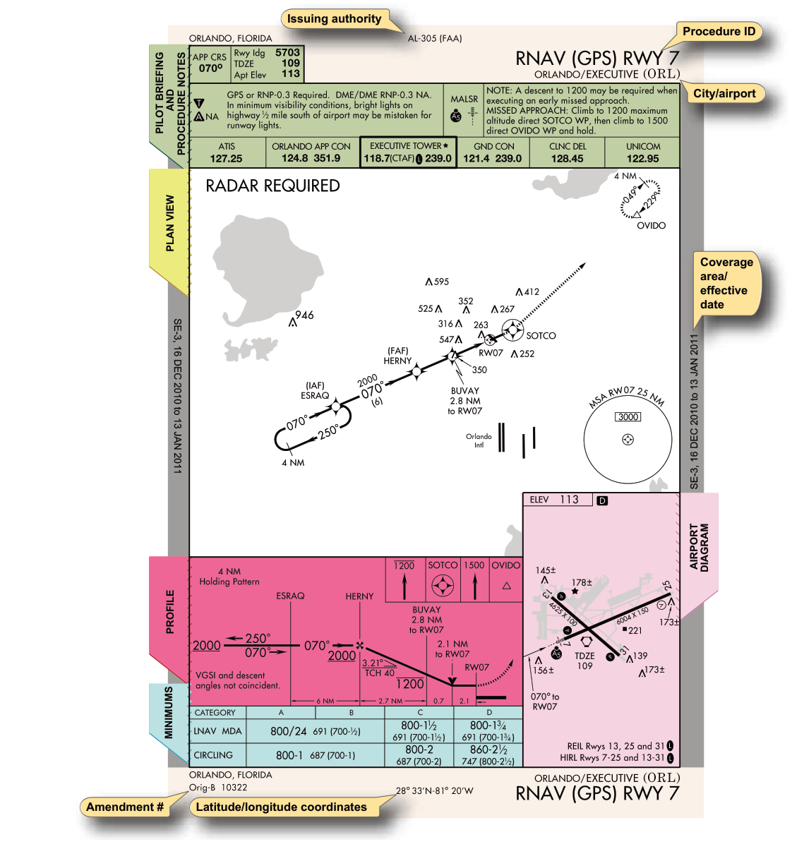
Every instrument approach procedure (IAP) is depicted on a standardized chart that packs an enormous amount of information into a compact format. For a pilot flying in IMC, this chart is the single most important piece of paper (or electronic display) in the cockpit. Understanding every symbol, abbreviation, and line style is not optional — misreading even one element can mean descending below a safe altitude or missing an approach entirely. This article walks through every major section of an instrument approach chart and explains what each symbol means, why it is there, and how to use it in the real world.
Instrument approach charts in the United States are produced primarily by the FAA's Aeronautical Information Services and are available through the National Aeronautical Charting Office (NACO/FAA). Jeppesen also publishes commercially formatted charts, but the FAA-format (government) charts are the ones directly referenced in FAA handbooks and on the instrument knowledge test. The layout of every government-format IAP chart follows a consistent top-to-bottom structure: briefing strip / header, plan view, profile view, airport sketch, and minimums section. Learning this structure as a framework makes every chart immediately navigable.
The Briefing Strip and Header
The top of every chart contains critical administrative and procedural data that should be reviewed during approach briefing. Key elements include:
- Approach type and runway: For example, "ILS OR LOC RWY 28L" tells you the approach type, any alternate approach (LOC in this case), and the landing runway.
- Airport name, city, state, and ICAO/FAA identifier: Used to confirm you have the correct chart.
- MSA circle (Minimum Safe Altitude): Sometimes shown in the upper corner of the plan view rather than the header. The MSA provides 1,000 feet of obstacle clearance within 25 nautical miles of the navaid or waypoint shown, divided into sectors. It is for emergency use only — it does not guarantee navaid reception or ATC separation.
- Procedure amendment and effective date: Always verify you are using a current chart. An expired chart is not legal for flight.
- Communications frequencies: ATIS, approach control, tower, ground, and CTAF are listed in order of use. Some charts show a "NOTES" box for non-standard items such as special climb gradients or alternate minimums not standard.
Plan View Symbols
The plan view is the bird's-eye map of the approach. It shows the area from overhead, centered on the airport or the primary navaid. Understanding the symbols here is essential for situational awareness before and during the approach.
Navaid and Fix Symbols
- VOR symbol: A compass-rose hexagon with a dot in the center. The identifier, frequency, and Morse code are printed beside it.
- NDB symbol: A circle with dots radiating outward like a stylized antenna. NDBs are now rare but still appear on legacy approach charts.
- Waypoint (RNAV fix): A five-pointed star outline (non-compulsory) or a solid five-pointed star (compulsory/mandatory reporting point). Compulsory fixes must be crossed at the charted altitude.
- Localizer depiction: A feather-like arrowhead symbol pointing toward the runway, with tick marks representing the localizer front course. The localizer identifier (e.g., I-ORD) and frequency (e.g., 109.9) are shown nearby.
- Glide slope intercept: Shown in the plan view as the point where the final approach fix (FAF) is located for precision approaches.
Course Lines and Arcs
The final approach course is shown as a bold line aligned with the runway extended centerline, labeled with the magnetic course. Procedure turns are depicted with a barbed arrow on one side of the course, indicating the direction of the outbound leg and the turn. If a procedure turn is not authorized, the symbol "NoPT" appears on the plan view, or a "straight-in" notation is provided. A holding-in-lieu of procedure turn (HILPT) is shown with the standard holding pattern symbol — a racetrack oval with an arrow indicating direction — at the IAF or FAF. DME arcs appear as a curved dashed line at a specified radius from the navaid, labeled with the arc radius (e.g., "17 DME").
Altitude and Obstacle Data
Spot elevations of significant obstacles appear as small X symbols with an elevation number. The Maximum Elevation Figure (MEF) from the sectional is not shown on approach charts, but the chart's obstacle data serves a similar function within the approach environment. Shaded or screened areas indicate mountainous or high-terrain regions requiring special attention. The procedure altitude at the IAF is printed alongside the fix symbol and represents the minimum altitude at which you should cross that fix.
Profile View Symbols
Directly below the plan view is the profile view — a side-elevation depiction of the approach from the IAF to the missed approach point (MAP). This is arguably the most operationally critical section of the chart.
- Glide slope depiction (ILS/GLS): A solid wedge line descending toward the runway threshold. The glide slope angle (typically 3.00°) and the crossing altitude at the outer marker or FAF are printed along this line.
- VASI/PAPI note: When a visual approach slope indicator is available, a note such as "VASI 3.00°" appears near the threshold in the profile view.
- Step-down fixes (non-precision): Shown as vertical lines crossing the approach course, each labeled with a fix name and a minimum crossing altitude. You may not descend below the step-down altitude until crossing that fix.
- Final Approach Fix (FAF): Depicted as a Maltese cross (a bold cross with flared ends) on non-precision approaches. On precision approaches (ILS), the FAF is where the glide slope intercept occurs, often at the outer marker, and is depicted differently — the Maltese cross is not used because the glide slope itself defines the descent path.
- Visual Descent Point (VDP): A small "V" symbol on the profile view. The VDP marks the point from which a normal 3° descent from MDA to the runway threshold is possible. Descending prior to the VDP may require a steeper-than-normal descent angle.
- Missed Approach Point (MAP): Shown as a bold vertical line at the runway threshold (for ILS) or at a specific fix/time/distance for non-precision approaches. At or before the MAP, if you do not have the required visual references, you must execute the missed approach immediately.
- Threshold Crossing Height (TCH): The height above the runway threshold that the glide slope passes through, typically 50 feet for ILS approaches. This value ensures the aircraft's wheels will cross the threshold at the proper height.
The Airport Diagram (Sketch)
The small airport sketch in the lower right of the chart shows runway layout, lighting systems, and relevant landmarks. Touchdown zone elevation (TDZE) and airport elevation are both printed here. Runway end identifiers and their elevations help you confirm which runway you are landing on and calculate decision altitude references. Lighting legend symbols — such as MALSR, ALSF-2, REIL, PAPI — indicate the type of approach lighting system installed. These are critical for visibility minimums: certain minimums (like ¾ mile visibility) are only available when specific lighting systems are operative.
The Minimums Section
The minimums section at the bottom of the chart is where you determine the legal lowest altitude and visibility for each category of aircraft. Aircraft are categorized A through D (and occasionally E) based on 1.3 times the power-off stall speed in the landing configuration (Vso): Category A is less than 91 knots, Category B is 91 to less than 121 knots, Category C is 121 to less than 141 knots, Category D is 141 to less than 166 knots, and Category E is 166 knots or more.
For precision approaches (ILS), the minimums are expressed as a Decision Altitude (DA) in feet MSL and a visibility in statute miles or runway visual range (RVR) in feet. DA is the altitude at which you must decide to land or go missed — you cannot continue below it without the required visual references. For non-precision approaches, minimums use a Minimum Descent Altitude (MDA) — you may descend to MDA but must level off and fly at MDA until the MAP unless you have the runway environment in sight. RVR is expressed in hundreds of feet (e.g., RVR 2400 = 2,400 feet). When RVR is not available, a converted ground visibility in statute miles is substituted.
The abbreviation "N/A" in a minimums box means that category of approach is not authorized for that aircraft category. "C" in a circle next to minimums indicates a circling approach is authorized to a different runway. Circling minimums are always higher than straight-in minimums because they require additional obstacle clearance during the circling maneuver.
Key Numbers and Rules
- MSA provides 1,000 ft obstacle clearance within 25 NM of the reference fix — emergency use only.
- ILS glide slope is typically 3.00°; TCH is typically 50 feet.
- The Maltese cross = FAF on non-precision approaches only.
- DA (precision) — decide at the altitude. MDA (non-precision) — level off, fly to MAP.
- Aircraft categories based on 1.3 × Vso: A <91 kt, B 91 to <121 kt, C 121 to <141 kt, D 141 to <166 kt, E 166 kt or more.
- Circling minimums are always higher than straight-in minimums.
- "Alternate minimums not standard" note means the airport has non-standard alternate minimums — check the front section of the approach chart booklet.
Common Test Traps
- Maltese cross confusion: Students sometimes look for the Maltese cross on ILS approaches. The Maltese cross marks the FAF only on non-precision approaches — on an ILS, the FAF is the glide slope intercept altitude, not a separate symbol.
- DA vs. MDA: The FAA test frequently asks whether you level off at a minimum or decide at it. DA = decide and go missed if no visual contact; MDA = level off and continue to MAP at that altitude.
- MSA altitude use: The MSA is published for emergency orientation only. It does not guarantee navaid signal reception, ATC communication, or radar coverage.
- NoPT vs. HILPT: "NoPT" means the procedure turn is not authorized on that segment — you must fly the charted routing. A HILPT (racetrack oval) is required unless ATC issues a straight-in clearance.
- RVR vs. statute miles: RVR is measured electronically at specific points on the runway and is expressed in feet. When the question specifies RVR 1600, that is roughly ¼ statute mile — but you cannot directly substitute visibility for RVR unless specifically authorized by the chart or regulations.